AI technical title is built by Patsnap AI team. It summarizes the technical point description of the patent document.
A technology of liquid crystal media and compounds, which is applied in the field of liquid crystal displays and can solve problems such as high rotational viscosity
Active Publication Date: 2014-03-26
MERCK PATENT GMBH
View PDF15 Cites 28 Cited by
Summary
Abstract
Description
Claims
Application Information
AI Technical Summary
This helps you quickly interpret patents by identifying the three key elements:
Problems solved by technology
Method used
Benefits of technology
Problems solved by technology
However, high birefringenceliquid crystal materials known in the prior art generally also have high rotational viscosities at the same time, which in turn negatively affects the response time
Method used
Image
Click on the blue label to locate the original text in one second.
Reading with bidirectional positioning of images and text.
Examples
Embodiment
[0307] The following examples are intended to illustrate the invention without limiting it.
[0308] In this context, percentage data represent percentages by weight. All temperatures are expressed in degrees Celsius. m.p. means melting point, cl.p. = clearing point. Furthermore, C=crystalline state, N=nematic phase, S=smectic phase and I=isotropic phase. The data between these symbols represent the transition temperature. also,
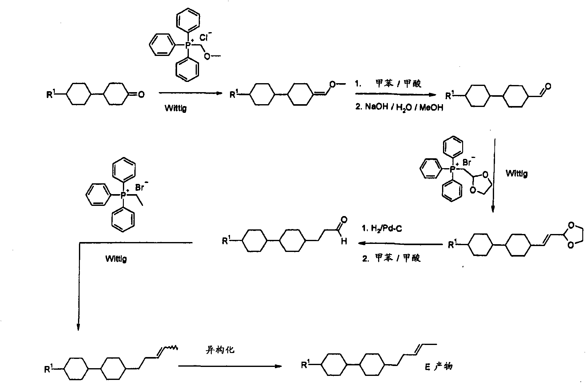
[0320] Mode The compound of is prepared according to the following scheme:
[0321]
[0322] C43S B 75N96.2I; Δn=0.0594; Δε=0.1; γ 1 =43mpa s;
[0323] K 1 =15.78; K 3 =19.56
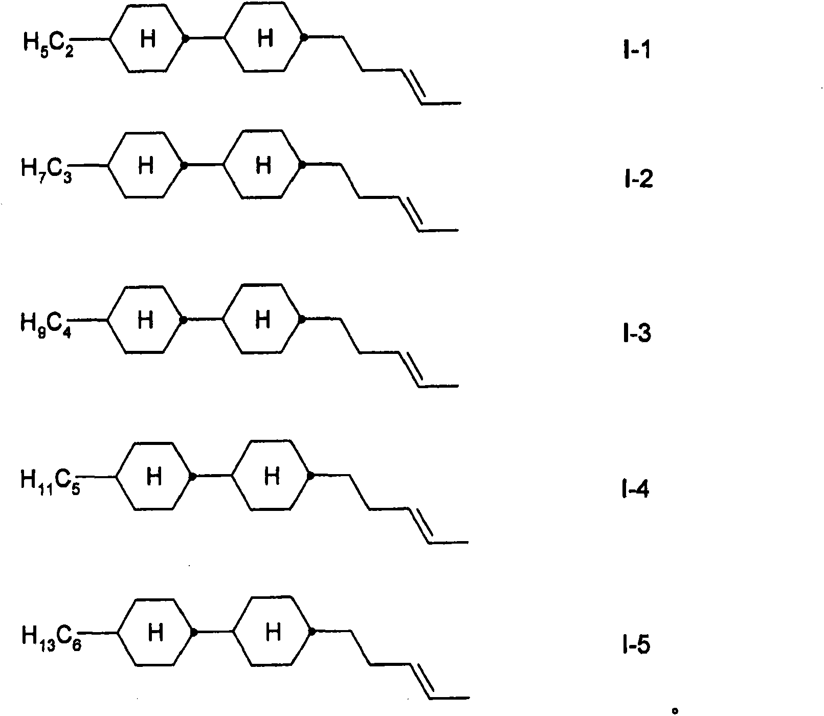
[0324] The following compounds were similarly prepared
[0325]
[0326] Mixture Example
[0327] Unless explicitly stated otherwise, electro-optical data were determined in a TN cell at 20°C at the first minimum (ie d·Δn value of 0.5 μm). Optical data are determined at 20°C unless expressly stated otherwise. All physical properties were determined according to "Merck Liquid Crystals, Physical Properties of Liquid Crystals", Status Nov. 1997, Merck KGaA, Germany and applied at a temperature of 20°C, unless expressly stated otherwise.
Embodiment M1
[0329]
PUM
Property
Measurement
Unit
refractive index
aaaaa
aaaaa
Abstract
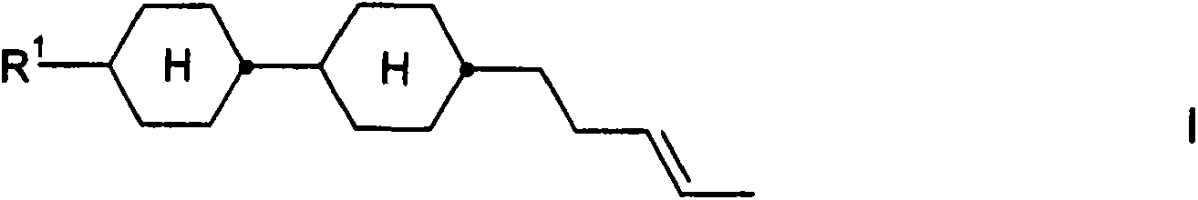
The invention relates to a liquid-crystalline medium comprising at least one compound of the formula I, in which R1 has the meanings indicated in claim 1, and to the use thereof in liquid-crystalline media and in electro-optical liquid-crystal displays.
Description
field of invention [0001] The invention relates to a liquid crystal medium (LC medium), its use for electro-optic purposes, and a liquid crystal display comprising this medium. Background technique [0002] Liquid crystals are mainly used as dielectrics in display devices because the optical properties of such substances can be affected by an applied voltage. Electro-optical devices based on liquid crystals are very well known to those skilled in the art and can be based on various effects. Examples of such devices are cells with dynamic scattering, DAP (deformation of aligned phases) cells, guest / host cells, TN cells with twisted nematic structure, STN (super twisted nematic) cells, SBE (Superbirefringence effect) box and OMI (Optical Mode Interference) box. The most common display devices are based on the Schadt-Helfrich effect and have a twisted nematic structure. Furthermore, there are cells which operate with an electric field parallel to the substrate and liquid cry...
Claims
Application Information
Patent Timeline
Application Date:The date an application was filed.
Publication Date:The date a patent or application was officially published.
First Publication Date:The earliest publication date of a patent with the same application number.
Issue Date:Publication date of the patent grant document.
PCT Entry Date:The Entry date of PCT National Phase.
Estimated Expiry Date:The statutory expiry date of a patent right according to the Patent Law, and it is the longest term of protection that the patent right can achieve without the termination of the patent right due to other reasons(Term extension factor has been taken into account ).
Invalid Date:Actual expiry date is based on effective date or publication date of legal transaction data of invalid patent.

