Pavement compacting vehicle

A technology of compaction device and wheel, applied in the field of road machinery, can solve the problems of slow speed, small working surface, increase the cost of road construction, etc., and achieve the effect of simple use and high compaction efficiency

Active Publication Date: 2014-03-26
TONGLING SANJIA TRANSFORMER
View PDF4 Cites 7 Cited by
  • Summary
  • Abstract
  • Description
  • Claims
  • Application Information

AI Technical Summary

Problems solved by technology

[0002] In road construction, the sand and gravel of the roadbed generally need to be tamped. The traditional tamping method uses a manually moved vibrating compactor or a large hydraulic tamping method. cost of pavement construction

Method used


Image

  • Pavement compacting vehicle

Examples


Embodiment Construction

[0016] Do further description below in conjunction with accompanying drawing:

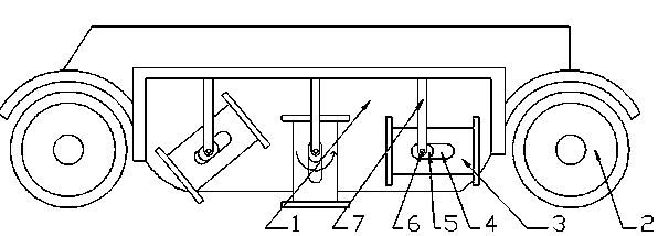
[0017] Such as figure 1 As shown, the present invention is a road compacting vehicle, the effective structure of the road compacting vehicle is a compacting device arranged in the middle of the wheel 2 of the vehicle, the compacting device is fixed on the chassis 1, and the compacting device is composed of several symmetrically distributed The vehicle chassis 1 is composed of cylindrical counterweights 3 on both sides. The tamping device also includes a number of rotating shafts 6. Two sliders 5 are fixedly connected to the rotating shafts 6. Two sliding blocks 5 are fixedly connected to the center of the counterweight 3. A groove 4 with the same width as the slider 5, the axis of the groove 4 is parallel to the central axis of the counterweight body 3, the length of the groove 4 is three times the length of the slider 5, and the slider 5 is connected to the slider 5. The groove 4 is slidingly con...


PUM


Abstract

The invention relates to a pavement compacting vehicle. A compacting device is arranged at the lower part of a vehicle chassis, and an engine drives an eccentric balance weight capable of sliding freely along a rotating shaft to rotate, so that the balance weight is constantly lifted and then slides during the moving process of the vehicle to continuously hammer the ground so as to compact a pavement. Compared with the traditional compacting device, the pavement compacting vehicle has the advantages that the use is simpler, the compacting efficiency is higher, and the more energy is saved as only one engine is used to supply energy.

Description

technical field [0001] The invention relates to a road compacting vehicle, which belongs to the field of road machinery. Background technique [0002] In road construction, the sand and gravel of the roadbed are generally compacted. The traditional compaction method uses a manually moved vibratory compaction machine or a large hydraulic compaction method. cost of road construction. Contents of the invention [0003] The purpose of the present invention is to provide a device that can conveniently and quickly tamp the road surface. [0004] The present invention is achieved in the following manner: [0005] A road compacting vehicle, comprising front and rear wheels and a chassis, the road compacting vehicle also includes a compacting device, the compacting device is fixed on the chassis of the vehicle and is located in the middle of the front and rear wheels; [0006] The tamping device is arranged symmetrically on both sides of the vehicle. The tamping device includes ...

Claims


Application Information

Patent Timeline
Patent Type & Authority Applications(China)
IPC IPC(8): E01C19/34
Inventor 徐国华
Owner TONGLING SANJIA TRANSFORMER
Why Eureka
Try Eureka