Full-automatic closed floor drain

A closed and fully automatic technology, applied in water/sludge/sewage treatment, indoor sanitary piping installations, drainage structures, etc., can solve problems such as difficult operation, slow drainage speed, and deodorization function, so as to reduce labor costs Operation, avoiding leakage, and lasting effect of drainage speed

Inactive Publication Date: 2014-03-26
韩昆
View PDF6 Cites 9 Cited by
  • Summary
  • Abstract
  • Description
  • Claims
  • Application Information

AI Technical Summary

Problems solved by technology

[0003] The floor drain of this structure has the defects of the following aspects: 1. The sewer pipe of the floor drain is at a vertical angle to the horizontal plane of the indoor ground, as shown in the attached manual. figure 1 As shown, in such a floor drain design, the sewer pipe 2 is at a vertical angle to the horizontal plane of the ground waterproof layer 1; at present, the waterproof treatment of the floor drain is usually realized by brushing the waterproof layer on the sewer pipe 2, because the sewer pipe 2 is perpendicular to the ground, brushing The waterproof layer is not easy to operate, and the protection of the waterproof layer is often not comprehensive when brushing the waterproof layer, so that water leaks from the junction of the sewer pipe of the floor drain and the ground waterproof layer 1; When the floor drain is not used for a long time, the water seal of the floor drain will dry up

Method used


Image

  • Full-automatic closed floor drain
  • Full-automatic closed floor drain
  • Full-automatic closed floor drain

Examples


Embodiment Construction

[0030] The following description will be made in conjunction with the accompanying drawings and specific implementation methods, the purpose is for the public to better understand the content, not to limit the content. In fact, the improvement of the floor drain with the same or similar principles , including its shape, size, material used, and the addition, subtraction or replacement of each component, all for the purpose of achieving basically the same effect, are all within the technical solution claimed by the present invention.

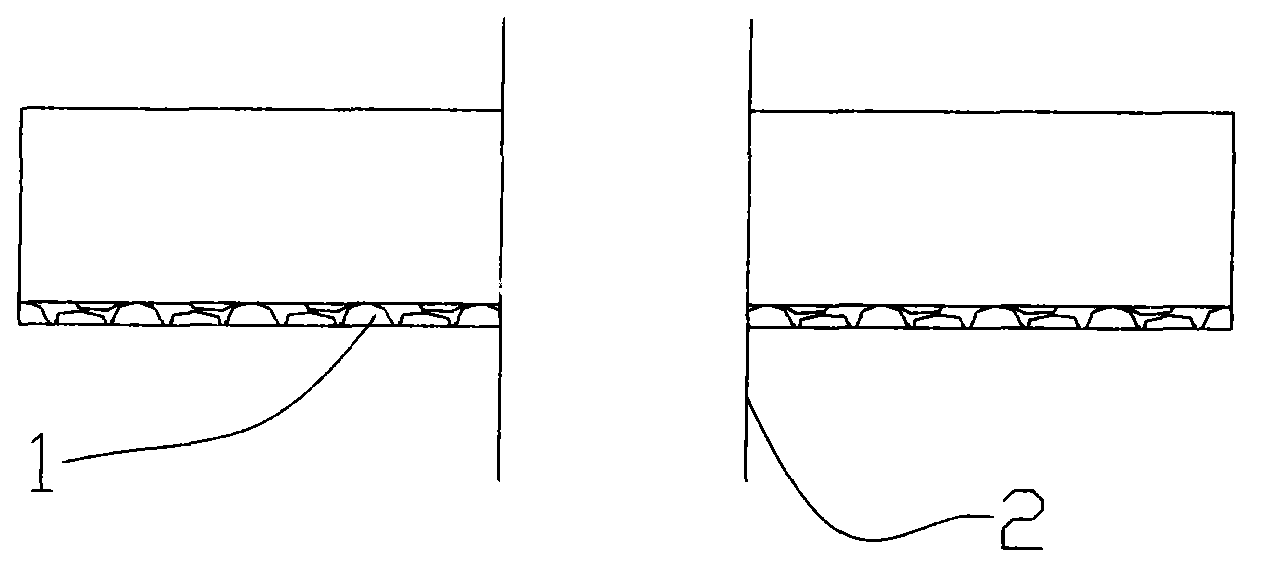
[0031] figure 1 It shows the waterproof design of the existing floor drain. As shown in the figure, the sewer pipe 2 is at a vertical angle to the horizontal plane of the ground waterproof layer 1. Since the sewer pipe 2 is perpendicular to the ground, it is not easy to operate when brushing the waterproof layer. When brushing the waterproof layer, it is often The protection of the waterproof layer is not comprehensive, so that water leaks from t...


PUM


Abstract

The invention discloses a floor drain which comprises an upper cover and an outer frame surrounding the outer side of the upper cover. A certain amount of running water gaps are arranged above the upper cover, and a floor drain body is arranged below the upper cover. A middle layer board is further arranged in the outer wall of the floor drain body, and the upper cover is connected with the middle layer board through a connection pillar. A clamping position provided with a concave portion extends upwards from the edge of the middle layer board, and a water seal can be formed by the clamping position and the downwards-protruding portion of the outer frame. A containing cavity for containing accumulated water is formed by the middle layer board, and a supporting pillar extends downwards from the bottom of the inner side of the middle layer board. A drainage hole is further formed in the middle layer board, the clamping position with a concave portion is arranged outside the drainage hole, and a water seal can be formed by the clamping position and the protruding portion of the bottom end of a drainage valve. Portions, opposite in position, of the middle layer board and the upper cover are provided with two sets of magnets respectively, wherein the magnets are opposite in magnetic pole. The magnet located below is provided with a guiding pillar, and a containing pillar is arranged on the outer side of the guiding pillar. The floor drain can be automatically opened according to the drainage amount, and the good water sealing and leakage preventing effects are achieved.

Description

technical field [0001] The invention relates to a floor drain, which can be automatically opened and closed according to the amount of water discharge, and is airtight when it is not in use, has a good deodorizing effect, and has the function of preventing leakage, and can meet the requirements of high-power drainage. needs. Background technique [0002] Most of the drainage floor drains currently used in the city, such as those installed in toilets or laundry rooms, have a simple structure, including a screen-like metal cover and a sewer pipe below. [0003] The floor drain of this structure has the defects of the following aspects: 1. The sewer pipe of the floor drain is at a vertical angle to the horizontal plane of the indoor ground, as shown in the attached manual. figure 1 As shown, in such a floor drain design, the sewer pipe 2 is at a vertical angle to the horizontal plane of the ground waterproof layer 1; at present, the waterproof treatment of the floor drain is u...

Claims


Application Information

Patent Timeline
IPC IPC(8): E03F5/04E03F5/14E03C1/282E03C1/29E03C1/294
Inventor 韩昆
Owner 韩昆
Why Eureka
Try Eureka