Pumping oil cylinder and pumping equipment provided with pumping oil cylinder

A pumping cylinder and pumping technology, which is applied in the field of pumping equipment and pumping cylinders, can solve problems such as low efficiency and troublesome operation

Active Publication Date: 2014-03-26
ZOOMLION HEAVY IND CO LTD
View PDF10 Cites 9 Cited by
  • Summary
  • Abstract
  • Description
  • Claims
  • Application Information

AI Technical Summary

Problems solved by technology

In the process of switching between high and low pressure, it is often necessary to switch the connection position of the rubber hose, or realize t

Method used


Image

  • Pumping oil cylinder and pumping equipment provided with pumping oil cylinder
  • Pumping oil cylinder and pumping equipment provided with pumping oil cylinder

Examples


Embodiment Construction

[0022] Hereinafter, the present invention will be described in detail with reference to the drawings and examples. It should be noted that, in the case of no conflict, the embodiments in the present application and the features in the embodiments can be combined with each other.

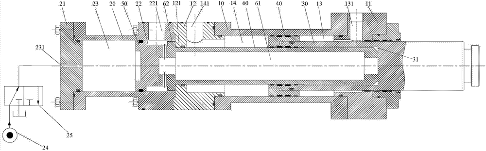
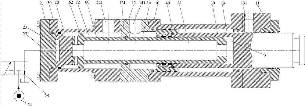
[0023] In this application, the end of the working cylinder where the rod cavity is located is the first end of the working cylinder, and the end of the working cylinder where the rodless cavity is located is the second end of the working cylinder.

[0024] Such as figure 1 and figure 2 As shown, according to an embodiment of the present invention, the pumping oil cylinder includes: a working cylinder, an inner stop ring 121 is provided on the inner wall of the working cylinder; a pumping piston rod 30, the first end of the pumping piston rod 30 extends out of the first end of the working cylinder Outside one end, and slidably arranged in the working cylinder, the second end of the pumping piston ...


PUM


Abstract

The invention provides a pumping oil cylinder and pumping equipment provided with the pumping oil cylinder. The pumping oil cylinder comprises a work cylinder, a pumping piston rod, a pumping piston, a positioning piston and a positioning piston rod, wherein an inner baffle ring, the pumping piston, the positioning piston, the positioning piston rod and the pumping piston rod divide the work cylinder into a first cavity, a second cavity, a third cavity and a fourth cavity, the first cavity, the second cavity, the third cavity and the fourth cavity are not communicated with one another, the second end of a rod inner cavity is communicated with the third cavity, and the work cylinder is provided with a first connecting port communicated with the first cavity, a second connecting port communicated with the second cavity, a third connecting port communicated with the third cavity and a fourth connecting port communicated with the fourth cavity. The pumping oil cylinder can achieve output of different pumping pressures simply and conveniently.

Description

technical field [0001] The invention relates to the field of pumping machinery, in particular to a pumping oil cylinder and pumping equipment including the pumping oil cylinder. Background technique [0002] In modern engineering construction, concrete pumping equipment is widely used to transport concrete. In the concrete pumping equipment, the concrete piston is driven by the reciprocating motion of a pair of pumping cylinders to realize the suction and discharge of concrete. [0003] The working environment of the concrete piston is harsh and often needs to be replaced. Therefore, the concrete piston should be easy to replace. When replacing the concrete piston, it is necessary to return the concrete piston to the water tank first, but in the normal working process, the concrete piston is not allowed to return to the position of the water tank. Therefore, the pumping cylinder needs to have two positions, one is the working state, at this time, the stroke of the oil cyli...

Claims


Application Information

Patent Timeline
IPC IPC(8): F15B15/14F15B15/20
Inventor 李沛林
Owner ZOOMLION HEAVY IND CO LTD
Why Eureka
Try Eureka