
Backlight module and display device

A backlight module and backplane technology, which is applied to lighting devices, fixed lighting devices, lighting device components, etc., can solve the problem of narrow frame and cannot be positioned

Active Publication Date: 2014-03-26
BOE TECH GRP CO LTD
View PDF7 Cites 9 Cited by
  • Summary
  • Abstract
  • Description
  • Claims
  • Application Information

AI Technical Summary

Problems solved by technology

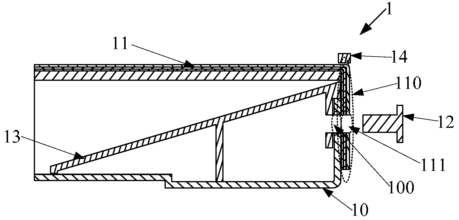
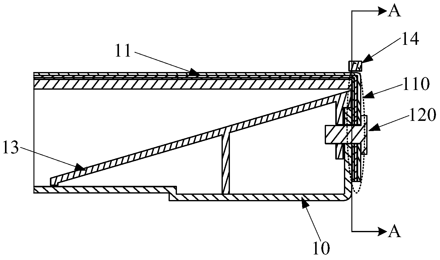
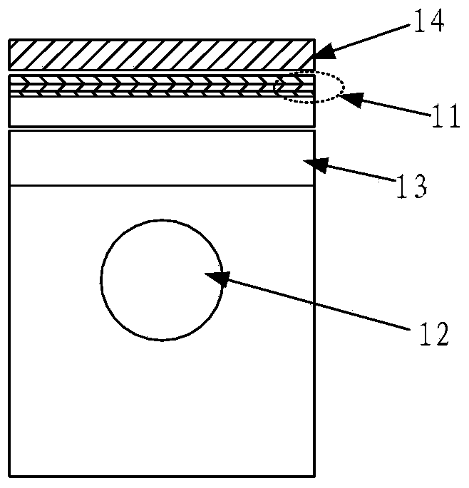
[0004] The embodiment of the present invention provides a backlight module and a display device, which solves the problem that the positioning cannot be performed due to the narrow frame when the film material is fixed in the direction perpendicular to the film material

Method used


Image

  • Backlight module and display device
  • Backlight module and display device
  • Backlight module and display device

Examples


Embodiment Construction

[0031] The following will clearly and completely describe the technical solutions in the embodiments of the present invention with reference to the accompanying drawings in the embodiments of the present invention. Obviously, the described embodiments are only some, not all, embodiments of the present invention. Based on the embodiments of the present invention, all other embodiments obtained by persons of ordinary skill in the art without making creative efforts belong to the protection scope of the present invention.

[0032] It should be noted that the terms "upper" and "lower" in the present invention are only used to describe the present invention with reference to the accompanying drawings, and are not used as limiting terms.

[0033] An embodiment of the present invention provides a backlight module, including:

[0034] Backplane;

[0035] a film material disposed above the back plate, the film material includes a bent portion; and

[0036] At least one film material ...


PUM

PropertyMeasurementUnit
thicknessaaaaaaaaaa

Abstract

An embodiment of the invention provides a backlight module and a display device, relates to the technical field of display, and solves the problem that membrane material cannot be positioned due to a narrow frame when fixed on the direction perpendicular to the membrane material. The backlight module comprises a backboard, the membrane material and at least one membrane material fixing structure. The membrane material is arranged on the backboard and comprises a bent part. The membrane material fixing structures are arranged on at least one side faces of the backboard, and the bent part of the membrane material is fixed on the backboard through the membrane material fixing structures.

Description

technical field [0001] The invention relates to the field of display technology, in particular to a backlight module and a display device. Background technique [0002] With the development of display technology, liquid crystal displays with narrow bezel design are becoming more and more popular. Liquid crystal displays can use Light Emitting Diode (LED for short) or Cold Cathode Fluorescent Lamp (CCFL for short) as their backlight, mainly including edge-lit and direct-lit. Wherein, in the edge-lit backlight, multiple point light sources are adjacently arranged on a straight line, and in the direct-lit backlight, multiple point light sources are evenly arranged on a plane. In order to prevent the movement and falling off of the optical film during the transportation and assembly of the backlight, it is necessary to design a fixed structure for the optical film. [0003] In the prior art, the fixing of the optical film is generally positioned through the film fixing hook in...

Claims


Application Information

Patent Timeline
Patent Type & Authority Applications(China)
IPC IPC(8): F21S8/00F21V17/12F21V17/16G02F1/13357
CPCG02F1/133608G02F2201/46G02F2201/54
Inventor 胡楠楠
Owner BOE TECH GRP CO LTD
Learn More