
Control device and control method of thermal power plant

A thermal power plant and control device technology, applied in the direction of total factory control, total factory control, electrical program control, etc., can solve problems such as changing control algorithms, and achieve the effect of suppressing the deterioration of characteristics

Active Publication Date: 2016-11-23
HITACHI LTD
View PDF5 Cites 0 Cited by
  • Summary
  • Abstract
  • Description
  • Claims
  • Application Information

AI Technical Summary

Problems solved by technology

However, when a thermal power plant is operated under unexpected conditions such as a change in the operating method of the thermal power plant or a change in the environment, it may be necessary to change the control algorithm, etc.

Method used


Image

  • Control device and control method of thermal power plant
  • Control device and control method of thermal power plant
  • Control device and control method of thermal power plant

Examples


Embodiment 1

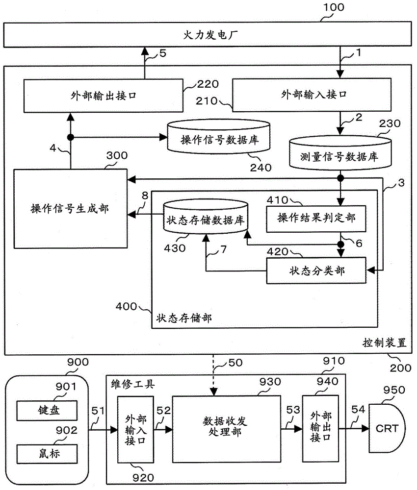
[0029] figure 1 It is a block diagram of the first embodiment of the control device of the thermal power plant. The control device 200 controls the thermal power plant 100 as a control object.

[0030] The control device 200 has an operation signal generation unit 300 , an operation result determination unit 410 , and a state classification unit 420 . The control device 200 has a measurement signal database 230 , an operation signal database 240 , and a state storage database 430 as databases. In addition, in this embodiment, the operation result determination unit 410 , the status classification unit 420 , and the status storage database 430 are collectively referred to as the status storage unit 400 .

[0031] In addition, the control device 200 has an external input interface 210 and an external output interface 220 as interfaces with the outside. The control device 200 inputs the measurement signal 1 from the thermal power plant 100 to the control device 200 via the ext...

Embodiment 2

[0148] Figure 9 It is a configuration diagram of the second embodiment of the control device 200 of the thermal power plant 100 . The control device 200 of the thermal power plant 100 of the present embodiment has a configuration in which an operation method learning unit 500 is added to the control device 200 of the thermal power plant 100 of the first embodiment.

[0149] The operation method learning unit 500 is constituted by a model 520 , an evaluation value calculation unit 530 , a calculation unit of the learning unit 540 , a model database 510 , and a database of learning information database 550 .

[0150] In the operation method learning unit 500 , the learning information database information 16 is obtained by referring to the measurement signal 3 .

[0151] The learning information database information 16 stored in the learning information database 550 is generated by the model 520 , the evaluation value calculation unit 530 , and the learning unit 540 .

[0152...

Embodiment 3

[0171] Figure 12 It is a block diagram of the third embodiment of the control device of the thermal power plant. The control device 200 of the thermal power plant 100 of the present embodiment is configured by adding a feature extraction unit 440 to the state storage unit 400 of the control device 200 of the thermal power plant 100 of the second embodiment.

[0172] The feature extraction unit 440 compares the result of the operation and the improvement and deterioration of the characteristics of the thermal power plant 100 to extract data items of the operation signal 5 that generate characteristic differences in the state of the thermal power plant 100 . Model accuracy is improved by adding the extracted data items to the model input items of the model 520 .

[0173] Figure 13 It is a figure explaining the operation|movement of the control apparatus 200 of this Example.

[0174] Figure 13 (a) is a diagram explaining the operation of the feature extraction unit 440 . ...


PUM


Abstract

PROBLEM TO BE SOLVED: To suppress deterioration of characteristics of a thermal power plant when an operation form or an environment changes.SOLUTION: A control device for a thermal power plant, which generates a first operation signal by referring to a measurement signal, includes an operation result determination part 410 for determining improvement / deterioration of characteristics of the thermal power plant as the result of outputting a first operation signal, a state classification part 420 for classifying the state of the thermal power plant by referring to the measurement signal, and a state storage database 430 for recording the determination result of the operation result determination part and the state of the thermal power plant classified by the state classification part in association with each other. Operation signal generation means continuously outputs the first operation signal currently output to the thermal power plant when the current state of the thermal power plant classified by the state classification part is a state when a second operation signal is generated reaching a state where the characteristics of the thermal power plant are determined to be worse by the operation result determination part.

Description

technical field [0001] The invention relates to a control device for a thermal power plant. In particular, it relates to a control device suitable for reducing environmental load substances discharged from thermal power plants and reducing fuel consumption. Background technique [0002] In the thermal power plant control device market, a technology is sought to reduce the environmental impact substances discharged from the thermal power plant and reduce the fuel flow rate consumed by the thermal power plant in order to reduce the operating cost of the thermal power plant. [0003] In the thermal power plant control device, a measurement signal obtained from the thermal power plant to be controlled and indicating the state of the thermal power plant is processed, and an operation signal to be given to the control target is calculated. Algorithms for calculating operating signals in order to make the measured signals of the thermal power plant meet their target values ​​are i...

Claims


Application Information

Patent Timeline
Patent Type & Authority Patents(China)
IPC IPC(8): G05B19/418
CPCY02P90/02
Inventor 关合孝朗楠见尚弘林喜治铃木佳奈子武内洋人北川胜秀赤津彻深井雅之朝仓一安
Owner HITACHI LTD
Features
  • Generate Ideas
  • Intellectual Property
  • Life Sciences
  • Materials
  • Tech Scout
  • Unparalleled Data Quality
  • Higher Quality Content
  • 60% Fewer Hallucinations
Learn More