
Oscillation circuit

An oscillation circuit and resonant circuit technology, applied in power oscillators, electrical components, automatic power control, etc., can solve the problems of characteristic deterioration, substrate potential variation, and oscillation signal purity deterioration, and achieve the effect of suppressing characteristic deterioration.

Active Publication Date: 2012-05-16
LAPIS SEMICON CO LTD
View PDF9 Cites 0 Cited by
  • Summary
  • Abstract
  • Description
  • Claims
  • Application Information

AI Technical Summary

Problems solved by technology

[0014] When such a high-frequency current flows in the resonant circuit, electromagnetic waves are emitted from the conductive material constituting the current path of the resonant circuit, and the substrate potential of the semiconductor element fluctuates, deteriorating the characteristics of other circuits in the semiconductor integrated circuit
For example, the characteristics of semiconductor integrated circuits that cause a drop in so-called reception sensitivity deteriorate
[0015] In order to solve the above problems, it is conceivable to reduce the oscillation amplitude, but if the oscillation amplitude is reduced, the purity of the oscillation signal will deteriorate, so it is difficult to use this method
In addition, widening the interval between the oscillation circuit and other circuits, or providing a shield between the oscillation circuit and other circuits is considered, but it is difficult to use this method because the area and cost of the semiconductor integrated circuit increase.

Method used


Image

  • Oscillation circuit
  • Oscillation circuit
  • Oscillation circuit

Examples


Embodiment 1

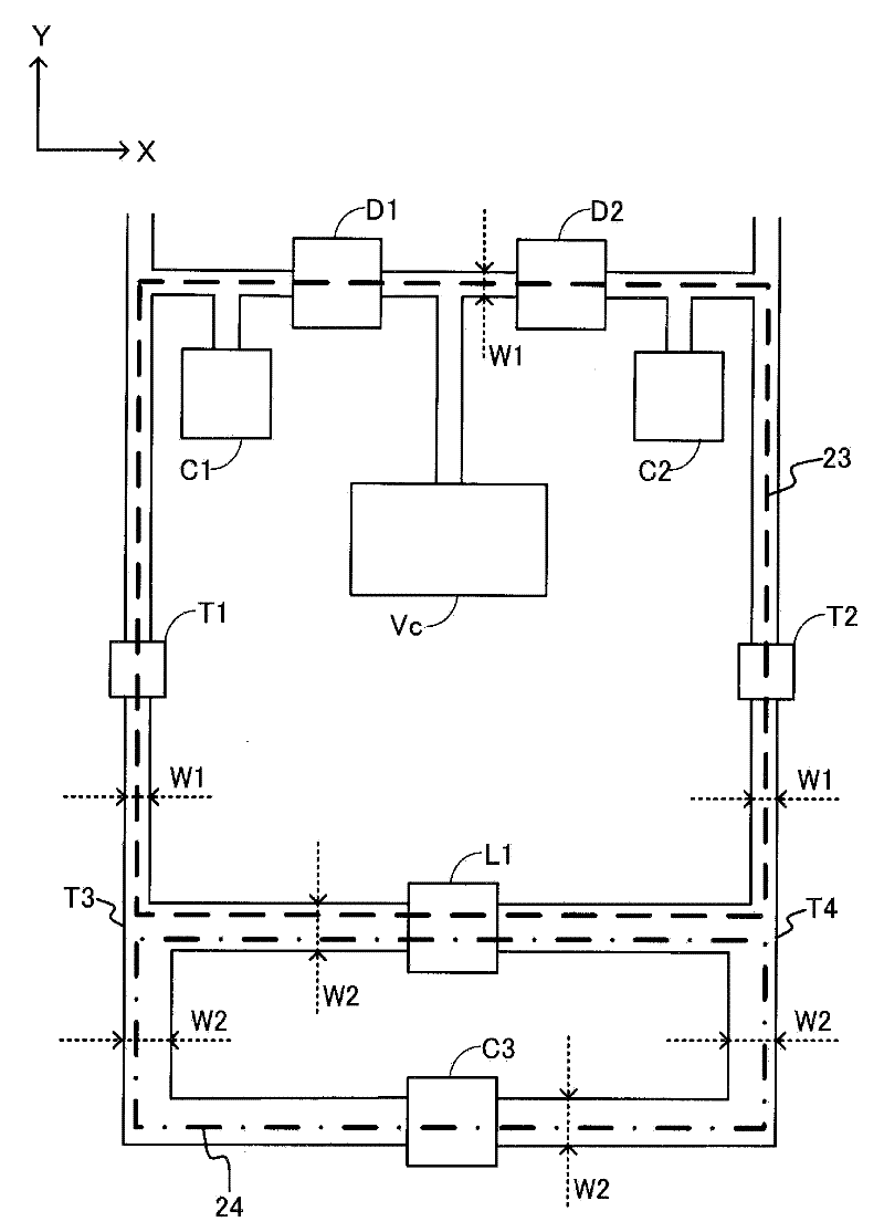
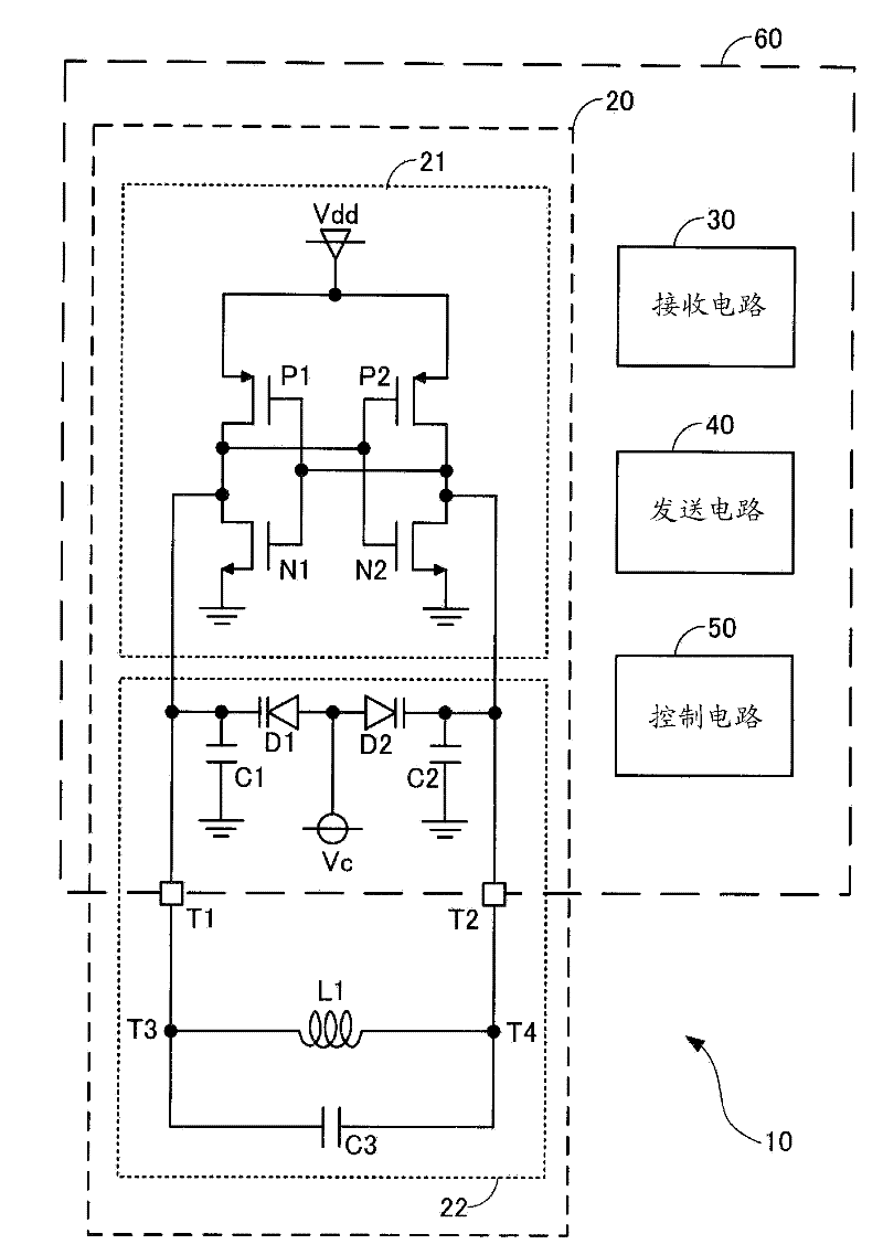
[0029] First, while referring to Figure 1 to Figure 3 , while describing the oscillation circuit of Embodiment 1 of the present invention. figure 1 It is an equivalent circuit diagram of a wireless device including the oscillator circuit according to Embodiment 1 of the present invention. figure 2 It is a schematic configuration diagram of a resonant circuit constituting the oscillating circuit according to the first embodiment of the present invention. image 3 It is a schematic configuration diagram for explaining a radio frequency magnetic field in a wireless device including the oscillator circuit according to the first embodiment of the present invention.

[0030] Such as figure 1 As shown, the wireless device 10 includes an oscillation circuit 20 , a reception circuit 30 , a transmission circuit 40 , and a control circuit 50 . In the wireless device 10 , part of the oscillation circuit 20 , the receiving circuit 30 , the transmitting circuit 40 , and the control cir...

Embodiment 2

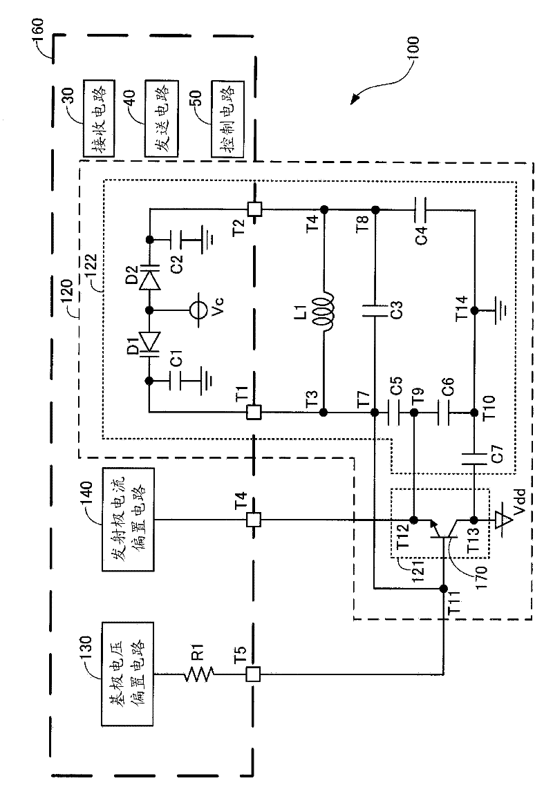
[0049] In the wireless device of the first embodiment, although the amplifier circuit constituting the oscillation circuit is provided inside the semiconductor integrated circuit, the amplifier circuit may be provided outside the semiconductor integrated circuit. while referring to Figure 4 as well as Figure 5 , the configuration of the wireless device in such a case will be described. Figure 4 is an equivalent circuit diagram of a wireless device equipped with an oscillation circuit according to Embodiment 2 of the present invention, Figure 5 is a schematic configuration diagram of an oscillation circuit according to Embodiment 2 of the present invention. Note that descriptions of the same members as those constituting the wireless device 10 of the first embodiment and the same configuration are omitted, and the same reference numerals are assigned in the drawings.

[0050] Such as Figure 4 As shown, the wireless device 100 includes an oscillation circuit 120 , a recei...


PUM


Abstract

An oscillation circuit includes a resonance circuit and an amplifier circuit. The resonance circuit includes an inner capacitor to be disposed inside a semiconductor integrated circuit, and an outer capacitor and an outer inductor to be disposed outside the semiconductor integrated circuit. The amplifier circuit includes an input terminal and an output terminal both connected to the resonance circuit. Further, the resonance circuit includes a first closed circuit portion including the inner capacitor, the outer inductor, and a first wiring portion for connecting the inner capacitor and the outer inductor. The resonance circuit further includes a second closed circuit portion including the outer capacitor, the outer inductor, and a second wiring portion for connecting the outer capacitor and the outer inductor. The second closed circuit portion has a wiring resistance smaller than that of the first closed circuit portion.

Description

technical field [0001] The present invention relates to an oscillation circuit capable of high frequency oscillation. Background technique [0002] Conventionally, an oscillation circuit composed of a resonant circuit composed of an inductor and a capacitor and a transistor has been used in a wireless device. By using a varactor diode as a capacitor, a voltage-controlled oscillator circuit (VCO: voltage controlled oscillator, voltage-controlled oscillator) is configured, and frequency control is possible. In addition, a phase synchronization circuit (PLL: Phase-locked loop, phase-locked loop) can be formed by this voltage-controlled oscillation circuit, a phase comparator, a loop filter, and a frequency divider, and can be used in a PLL frequency synthesizer. [0003] In recent years, oscillation circuits as described above have been formed as part of semiconductor integrated circuits. As a method of forming an oscillation circuit as a part of a semiconductor integrated ci...

Claims


Application Information

Patent Timeline
Patent Type & Authority Applications(China)
IPC IPC(8): H03L7/099
CPCH03B5/1243H03B5/1228H03B5/1212H03L7/099
Inventor 太矢隆士
Owner LAPIS SEMICON CO LTD
Features
  • Generate Ideas
  • Intellectual Property
  • Life Sciences
  • Materials
  • Tech Scout
  • Unparalleled Data Quality
  • Higher Quality Content
  • 60% Fewer Hallucinations
Learn More