An isolating grounding switch

A technology of isolating grounding switch and grounding switch, which is applied in switchgear, switchgear setting, electrical components, etc., can solve the problems of reducing the isolation grounding switch, the inability of both sides of the disconnection switch to be grounded at the same time, and the large volume of the isolating grounding switch. Achieve the effect of volume reduction, easy grounding, stable and reliable movement

Active Publication Date: 2016-03-30
KUNMING UNIV OF SCI & TECH
View PDF6 Cites 0 Cited by
  • Summary
  • Abstract
  • Description
  • Claims
  • Application Information

AI Technical Summary

Problems solved by technology

[0003] The technical problem to be solved by the present invention is to provide an isolating grounding switch with a simple and compact structure, both sides of the isolating switch fracture can be grounded at the same time during line maintenance, and can reduce contact wear and tear, so as to solve the problem of the existing isolating grounding switch with large volume and isolating switch fracture. The problem that both sides cannot be grounded at the same time

Method used


Image

  • An isolating grounding switch
  • An isolating grounding switch
  • An isolating grounding switch

Examples


Embodiment 1

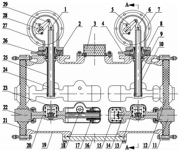
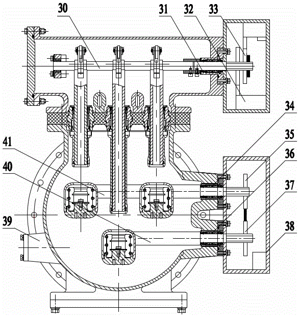
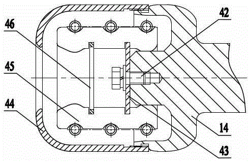
[0027] Embodiment 1: as Figure 1-3 As shown, an isolating grounding switch includes three parts: isolating switch, grounding switch I, and grounding switch II, specifically including connecting rod I1, insulating basin I2, desiccant 3, grounding terminal II4, crank arm II5, connecting rod II6, Grounding shell II7, insulating basin II8, earthing switch movable contact II9, earthing switch movable contact shield II10, body insert I11, disc insulator I12, earthing switch static contact II13, static side conductor 14, isolating switch static contact Head 15, cover plate 16, rack moving contact rod 17, gear 18, metal shell 19, moving side conductor 20, disc insulator II21, body insert II22, grounding switch static contact I23, earthing switch moving contact I24, Earthing switch moving contact shield cover Ⅰ25, grounding terminal Ⅰ26, grounding shell Ⅰ27, transmission shaft Ⅰ28, crank arm Ⅰ29, transmission shaft Ⅱ30, shaft seal Ⅰ31, operating mechanism box Ⅰ32, locking lever Ⅰ33, s...

Embodiment 2

[0035] Embodiment 2: as Figure 1-3As shown, an isolating grounding switch includes three parts: isolating switch, grounding switch I, and grounding switch II, specifically including connecting rod I1, insulating basin I2, desiccant 3, grounding terminal II4, crank arm II5, connecting rod II6, Grounding shell II7, insulating basin II8, earthing switch movable contact II9, earthing switch movable contact shield II10, body insert I11, disc insulator I12, earthing switch static contact II13, static side conductor 14, isolating switch static contact Head 15, cover plate 16, rack moving contact rod 17, gear 18, metal shell 19, moving side conductor 20, disc insulator II21, body insert II22, grounding switch static contact I23, earthing switch moving contact I24, Earthing switch moving contact shield cover Ⅰ25, grounding terminal Ⅰ26, grounding shell Ⅰ27, transmission shaft Ⅰ28, crank arm Ⅰ29, transmission shaft Ⅱ30, shaft seal Ⅰ31, operating mechanism box Ⅰ32, locking lever Ⅰ33, sh...


PUM


Abstract

The invention relates to an isolated earth switch and belongs to the technical field of high-voltage power transmission. The isolated earth switch comprises a metal shell, an isolating switch, an earth switch I, an earth switch II and the like, wherein the isolating switch comprises a body embedding member, a disk-shaped insulator, a fixed-side conductor, an isolating switch fixed contact, a rack movable touch rod, a gear and a movable-side conductor; the two earth switches include disc-shaped insulator body embedding members, movable-side conductors, earth switch fixed contacts, earth switch movable contacts, earth switch movable contact shielding cases, earthing terminals, earthing shells and insulating basins. The isolated earth switch has the characteristics of simple and compact structure, high reliability and the like, is capable of earthing the buses at the two sides of breaks of the isolating switch safely and synchronously, reducing the problem of serious abrasion of the contacts when the isolating switch and the earth switches are switched on and switched off, achieving steady and reliable motion of the movable contacts of the isolating switches and rapid and convenient earthing of the movable contacts of the earth switches, and is suitable for popularization and application.

Description

technical field [0001] The invention relates to an isolating grounding switch, in particular to a three-phase common box-type isolating grounding switch for gas-insulated metal-enclosed switchgear, and belongs to the technical field of high-voltage power transmission. Background technique [0002] The isolating earthing switch is usually used in gas-insulated metal-enclosed switchgear (GIS) or composite electrical (PASS). It is not a separate product and is usually installed before and after the circuit breaker. At present, there are two main types of isolating and grounding switches that are common in the market: one is the traditional three-phase split cylinder structure, and the isolating switch and the grounding switch are separate GIS components. The three-phase split cylinder structure greatly increases the overall size of the GIS, and at the same time the manufacturing cost also increases; the other is that various manufacturers have introduced three-phase common box ...

Claims


Application Information

Patent Timeline
Patent Type & Authority Patents(China)
IPC IPC(8): H02B13/075
Inventor 游贤衡张宇徐海华董涛杨亮王子威
Owner KUNMING UNIV OF SCI & TECH
Why Eureka
Try Eureka