
A method for identification of transformer excitation inrush current based on multi-fractal spectrum

A multi-fractal spectrum and excitation inrush current technology, applied in electrical components, emergency protection circuit devices, etc., can solve the problems of misjudgment, difficulty in protection setting, improvement degree and applicability, etc.

Active Publication Date: 2017-02-22
KUNMING UNIV OF SCI & TECH
View PDF3 Cites 0 Cited by
  • Summary
  • Abstract
  • Description
  • Claims
  • Application Information

AI Technical Summary

Problems solved by technology

The protection setting of the above various principles is relatively difficult. In the application, the intelligence is set or corrected through experiments according to the actual situation, and there is a hidden danger of misjudgment.
Therefore, there are many kinds of excitation inrush current identification methods, but the degree of perfection and applicability still need to be improved.

Method used


Image

  • A method for identification of transformer excitation inrush current based on multi-fractal spectrum
  • A method for identification of transformer excitation inrush current based on multi-fractal spectrum
  • A method for identification of transformer excitation inrush current based on multi-fractal spectrum

Examples


Embodiment approach 1

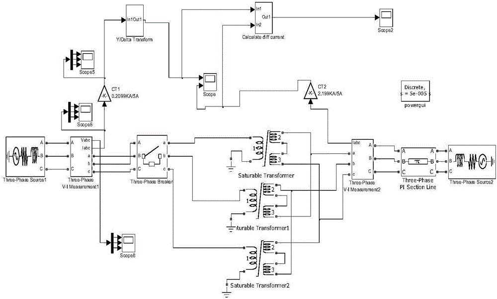
[0081] Implementation mode 1: figure 1 In the simulation system shown, the transformers are three single-phase three-winding transformers with Yd11 connection. The high-voltage winding connected to the 110kV system is the primary side of the transformer, and the medium-voltage winding and the low-voltage winding are cascaded to form the secondary side of the transformer. The transmission line is simulated by 5 sections of π-type equivalent circuit, each section is 4km long. The parameters of the transformer simulation system are shown in Table 1, and the parameters of the magnetization curve are shown in Table 2.

[0082] Table 1 Simulation system parameters

[0083]

[0084] Table 2 Magnetization parameters

[0085]

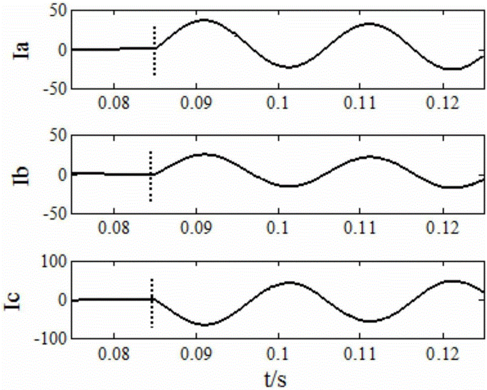
[0086] When there is a short-circuit fault between phases A and B at the outlet of the transformer, the fault angle is 0°, and the transition resistance is 0.1Ω:

[0087] (1) The differential current of the transformer is greater than the set value, a...

Embodiment approach 2

[0098] Embodiment 2: The simulation system and transformer parameters are the same as Embodiment 1.

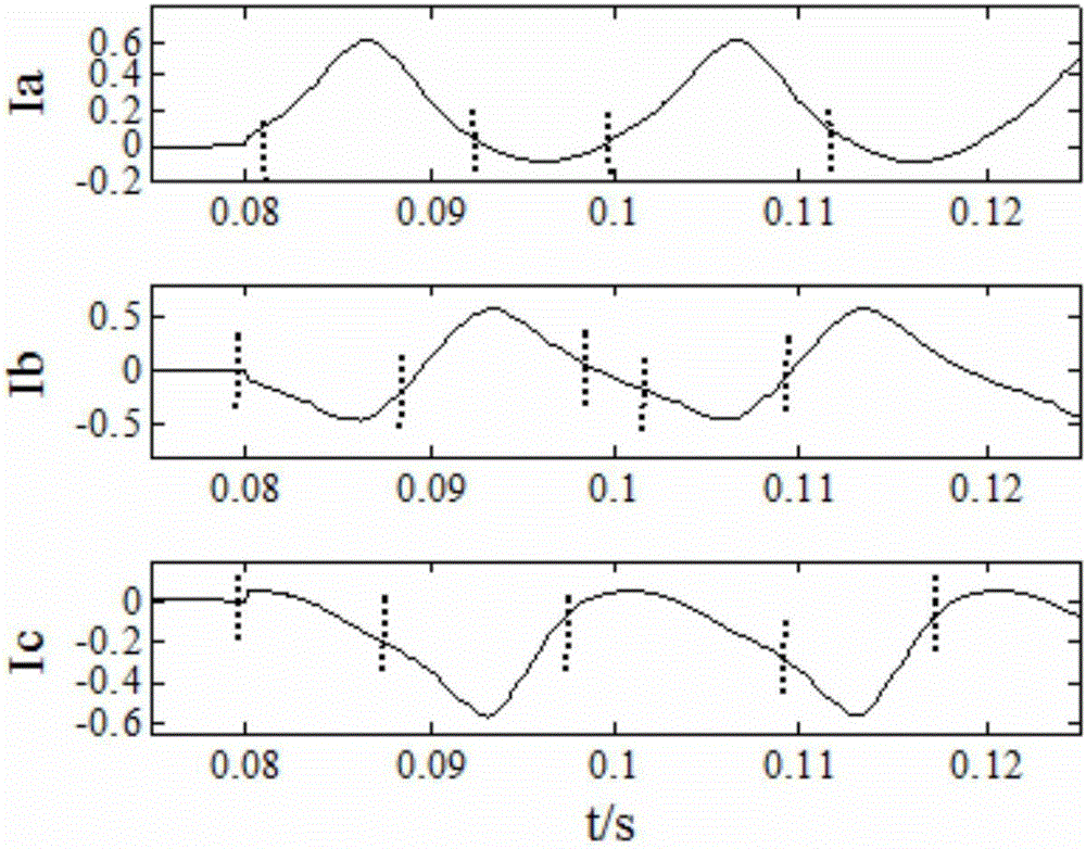
[0099] The transformer is switched on without load, and the switching angle is 45°, and the calculation and statistics are carried out in the same way as in Embodiment 1. and They are 0.6881 and 2.2731 respectively, and the calculated unevenness of mass density distribution =1.5850>1.25, the excitation inrush current is correctly identified, and the protection is blocked.


PUM


Abstract

The invention relates to a transformer excitation surge current discriminating method based on multi-factional spectrums, and belongs to the technical field of transformer relay protection. When the differential current of a transformer is greater than a set value, a differential current oscillogram is divided into several regions or subsets along a time axis direction. A difference between a maximum value and a minimum value of the differential value in each region is defined as delta[i]cd. Conditions of distribution of the delta[i]cd in each region are defined as a quality distribution probability P [i](epsilon) of the multi-factional spectrums, and a non-uniformity degree (delta alpha) of the quality distribution probability distribution of each subclass is utilized to discriminate excitation surge currents. The transformer excitation surge current discriminating method based on the multi-factional spectrums of the invention is different from traditional surge current discriminating methods which only utilize single characteristic amounts. According to the invention, multiple information such as amplitudes, phases and singularity of the differential currents are fused; higher reliability is provided; a sampling frequency of the method is 20kHz; a time window is 20ms; a required data length is relatively short; and hardware implementation is facilitated.

Description

technical field [0001] The invention relates to a transformer excitation inrush current identification method based on a multi-fractal spectrum, and belongs to the technical field of transformer relay protection. Background technique [0002] Transformer is an indispensable and important equipment in the power system to connect networks with different voltage levels, and its safe operation is directly related to whether the entire power system can work stably and continuously. There are many types of transformer protection. Among many types of transformer protection, longitudinal differential protection can better meet the requirements of selectivity, quick action, sensitivity and reliability in relay protection, and is the main form of transformer main protection. The longitudinal difference protection uses the difference between the primary side current and the secondary side current of the transformer as the differential current, and if the differential current exceeds a ...

Claims


Application Information

Patent Timeline
Patent Type & Authority Patents(China)
IPC IPC(8): H02H7/045
Inventor 束洪春张兰兰安娜
Owner KUNMING UNIV OF SCI & TECH
Learn More