Permanent magnet finite angle motor without magnetic yoke structure
A technology with limited rotation angle and yoke structure, applied in the direction of magnetic circuit shape/style/structure, magnetic circuit rotating parts, electric components, etc., can solve the problems of low air gap magnetic density, low power density, slow response speed, etc., to achieve Effects of reduced weight, reduced moment of inertia, and improved response speed
- Summary
- Abstract
- Description
- Claims
- Application Information
AI Technical Summary
Problems solved by technology
Method used
Image
Examples
specific Embodiment approach 1
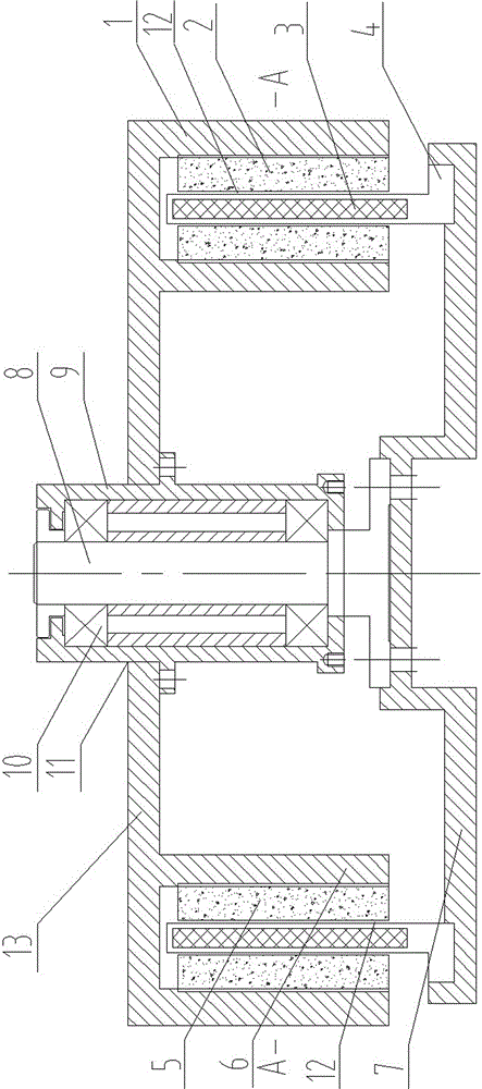
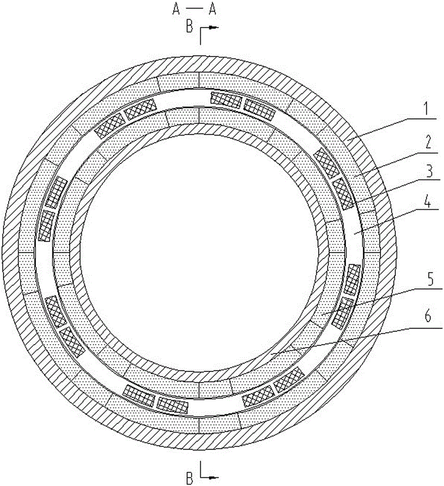
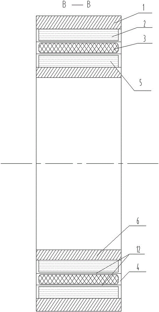
[0021] Specific implementation mode one: as Figure 1 to Figure 5 As shown: permanent magnet finite angle motor without magnetic yoke structure, said permanent magnet finite angle motor without magnetic yoke structure includes inner rotor 6, outer rotor 1, inner permanent magnet 2, outer permanent magnet 5. The motor shaft 8 and the bearing seat 9; the inner rotor 6 and the outer rotor 1 are fixed together, the motor shaft 8 is installed in the bearing seat 9 through the bearing 10, the center hole 11 is provided in the middle of the outer rotor 1, and the bearing seat 9 is installed outside In the central hole 11 of the rotor 1, it is fixedly connected with the outer rotor 1, and the motor shaft 8 is arranged coaxially with the inner rotor 6 and the outer rotor 1. The permanent magnet type limited-angle motor without a magnetic yoke structure also includes the coreless type The stator, the coreless stator includes a skeleton 4, a support 7 and multiple sets of winding coils 3...
specific Embodiment approach 2
[0026] Specific implementation mode two: as Figure 1 to Figure 5 As shown in the specific embodiment 1 of the non-conductive yoke structure permanent magnet limited angle motor, the inner rotor 6 and the outer rotor 1 are made of aluminum, plastic or carbon fiber materials. The light weight reduces the moment of inertia of the motor and improves the response speed of the motor.
[0027] The working principle of the present invention is as follows:
[0028] When the winding coil 3 is fed with direct current, because the winding directions of the adjacent winding coils 3 on the skeleton 4 are opposite, then at a certain moment, the current direction in the winding coil 3 is as follows: Figure 4 As shown, the magnetization method of the closed magnetic circuit is as follows Figure 5 As shown, this annular closed magnetic circuit structure can effectively increase the air gap magnetic density of the motor, thereby increasing the torque density of the motor, and the torque den...
PUM
 Abstract
Description
Claims
Application Information
 - R&D
- Intellectual Property
- Life Sciences
- Materials
- Tech Scout
- Unparalleled Data Quality
- Higher Quality Content
- 60% Fewer Hallucinations
Browse by: Latest US Patents, China's latest patents, Technical Efficacy Thesaurus, Application Domain, Technology Topic, Popular Technical Reports.
© 2025 PatSnap. All rights reserved.Legal|Privacy policy|Modern Slavery Act Transparency Statement|Sitemap|About US| Contact US: help@patsnap.com


