Rotor and motor

A rotor and rotor core technology, applied in the direction of magnetic circuit rotating parts, magnetic circuit shape/style/structure, etc., can solve the problems of poor magnetic flux leakage reduction, complicated assembly process, and complicated rotor structure, etc., to improve the effective utilization The effect of improving the efficiency, improving the overall performance and simplifying the assembly process

Active Publication Date: 2015-11-18
GUANGDONG WELLING ELECTRIC MACHINE MFG +1
View PDF8 Cites 9 Cited by
  • Summary
  • Abstract
  • Description
  • Claims
  • Application Information

AI Technical Summary

Problems solved by technology

[0005] The purpose of the present invention is to overcome the shortcomings of the above-mentioned prior art, and provide a rotor and a motor, which solve the technical problems of the existing rotor with complex structure, complex assembly process, and poor effect of reducing magnetic flux leakage

Method used


Image

  • Rotor and motor
  • Rotor and motor
  • Rotor and motor

Examples


Embodiment 1

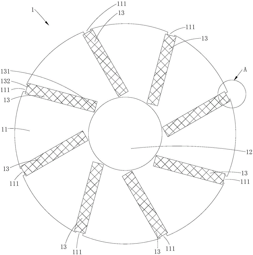
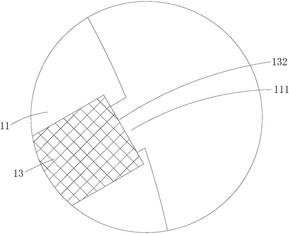
[0033] Such as figure 1 and figure 2 As shown, the rotor 1 provided by Embodiment 1 of the present invention includes a rotor core 11, a rotating shaft 12 installed at the center of the rotor core 11, and several magnets embedded in the rotor core 11 at intervals along the circumferential direction. Steel 13, the rotor core 11 is provided with several magnetic steel grooves for the accommodation and positioning of the magnetic steel 13, each magnetic steel 13 has an inner end 131 close to the rotating shaft 12 and an outer end 132 far away from the rotating shaft 12, the rotor iron core 11 There are also several outer magnetic bridge notches 111 recessed from the outer edge of the rotor core 11 and extending to the outer ends 132 of the magnetic steels 13 respectively. The rotor 1 provided in this embodiment cancels the setting of the magnetic isolation sleeve, thereby effectively simplifying the structure of the rotor 1, and because the assembly process of the magnetic isol...

Embodiment 2

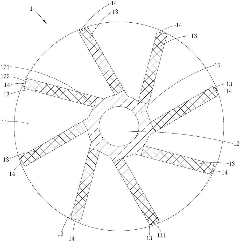
[0040] Such as image 3 and Figure 4 As shown, the same as the first embodiment, the rotor 1 provided by this embodiment also includes a rotor core 11, a rotating shaft 12 and several magnetic steels 13, each magnetic steel 13 also has an inner end 131 close to the rotating shaft 12 and an inner end 131 away from the rotating shaft 12. The outer end 132 of the rotating shaft 12 and the rotor iron core 11 are also provided with several magnetic steel grooves and a plurality of outer magnetic bridge gaps 111 recessed from the outer edge of the rotor iron core 11 and extending to the outer ends 132 of each magnetic steel 13; Different from Embodiment 1, the rotor core 11 of this embodiment is also provided with an inner magnetic bridge gap 112 located between the magnetic steel 13 and the rotating shaft 12, and the inner magnetic bridge gap 112 is injected and filled with an inner injection molded part 15 The outer magnetic bridge notch 111 is injected and filled with the outer...

Embodiment 3

[0044] Such as Figure 5 As shown, the same as the first embodiment, the rotor 1 provided by this embodiment also includes a rotor core 11, a rotating shaft 12 and several magnetic steels 13, each magnetic steel 13 also has an inner end 131 close to the rotating shaft 12 and an inner end 131 away from the rotating shaft 12. The outer end 132 of the rotating shaft 12 and the rotor iron core 11 are also provided with several magnetic steel grooves and a plurality of outer magnetic bridge gaps 111 recessed from the outer edge of the rotor iron core 11 and extending to the outer ends 132 of each magnetic steel 13; Different from the first embodiment, the rotor core 11 of this embodiment is also provided with a number of magnetic isolation bridges 114 distributed between the magnetic steel 13 and the rotating shaft 12 at intervals along the circumferential direction, so that through the magnetic isolation bridges 114 Setting, on the one hand, can further reduce the amount of magnet...


PUM


Abstract

The invention is suitable for the field of motors, and discloses a rotor and a motor. The rotor comprises a rotor core, a rotating shaft passing through the center of the rotor core, and a plurality of magnet steels which are embedded in the rotor core at intervals in a circumferential direction. The rotor core is provided with a plurality of magnet steel grooves which are used for the storage and positioning of the plurality of magnet steels. Each magnet steel is provided with an inner end close to the rotating shaft, and an outer end far from the rotating shaft. The rotor core is also provided with a plurality of outer magnetic bridge gaps which extend from the edge of the rotor core to the outer ends of the magnet steels in a concave manner. The rotor gets rid of a magnetic isolation sleeve, thereby effectively simplifying the structure of the rotor and the assembly technology of the rotor. Meanwhile, the outer edge of the rotor core is additionally provided with the outer magnetic bridge gaps, thereby opening an outer magnetic bridge of the rotor core, enabling more magnetic chains of the magnet steels to pass through a stator winding linkage, reducing the magnetic leakage of the rotor, greatly improving the effective utilization rate of the magnetic flux of the rotor, and finally achieving a purpose of improving the output capability of the motor.

Description

technical field [0001] The invention belongs to the field of motors, in particular to a rotor and a motor with the rotor. Background technique [0002] The existing tangential rotor structure generally includes a rotor core, magnetic steel, a magnetic isolation sleeve and a rotating shaft, and the rotor iron core is sleeved on the rotating shaft through a magnetic isolation sleeve. The existing tangential rotor structure is used in specific applications. The following deficiencies generally exist in: [0003] 1) The use of a magnetic isolation sleeve to connect the rotor core and the shaft will complicate the structure of the rotor and the assembly process, and will complicate the structure of the motor; in addition, the use of a magnetic isolation sleeve to reduce magnetic flux leakage can reduce leakage The magnetic effect is relatively poor. [0004] 2) The magnetic steel is generally arranged along the radial direction of the rotor iron core. In this way, the effective...

Claims


Application Information

Patent Timeline
Patent Type & Authority Applications(China)
IPC IPC(8): H02K1/27
Inventor 龚文胜王飞
Owner GUANGDONG WELLING ELECTRIC MACHINE MFG
Why Eureka
Try Eureka