Interference indication method and device under adjacent channel coexisting condition

A technology of adjacent frequency coexistence and adjacent frequency interference, which is applied in wireless communication, electrical components, network planning, etc., can solve the problems of system adjacent frequency coexistence, achieve the effects of improving system performance, reducing the number of indications, and reducing adjacent channel interference

Inactive Publication Date: 2014-03-26
NTT DOCOMO INC
View PDF0 Cites 0 Cited by
  • Summary
  • Abstract
  • Description
  • Claims
  • Application Information

AI Technical Summary

Problems solved by technology

Therefore, the coexistence of adjacent frequencies of two LTE systems is likely to occur

Method used


Image

  • Interference indication method and device under adjacent channel coexisting condition
  • Interference indication method and device under adjacent channel coexisting condition
  • Interference indication method and device under adjacent channel coexisting condition

Examples


Embodiment 1

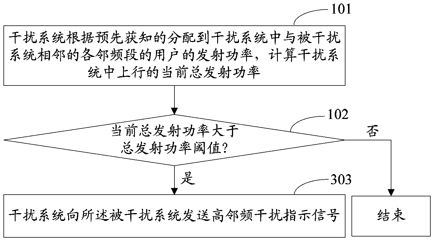
[0048] figure 1 It is an exemplary flow chart of the interference indication method under adjacent frequency coexistence in Embodiment 1 of the present invention. Such as figure 1 As shown, the method may include the following processing flow.

[0049] Step 101: The interfering system calculates the current total uplink transmit power in the interfering system according to the previously known transmit power of users in the adjacent frequency bands allocated to the interfering system and adjacent to the interfered system.

[0050] In this step, the transmit power of users allocated to each adjacent frequency band may be accumulated to obtain the current total uplink transmit power in the interference system.

[0051] It can also further determine the interference weighting coefficient corresponding to each frequency band according to the position relationship of each adjacent frequency band, and then multiply the transmission power of the users allocated to each adjacent frequency ba...

Embodiment 2

[0067] In the second embodiment, taking the case where interference weighting coefficients are set in each adjacent frequency band as an example, an example of the interference indicating method and device under the coexistence of adjacent frequencies of the first embodiment is respectively given.

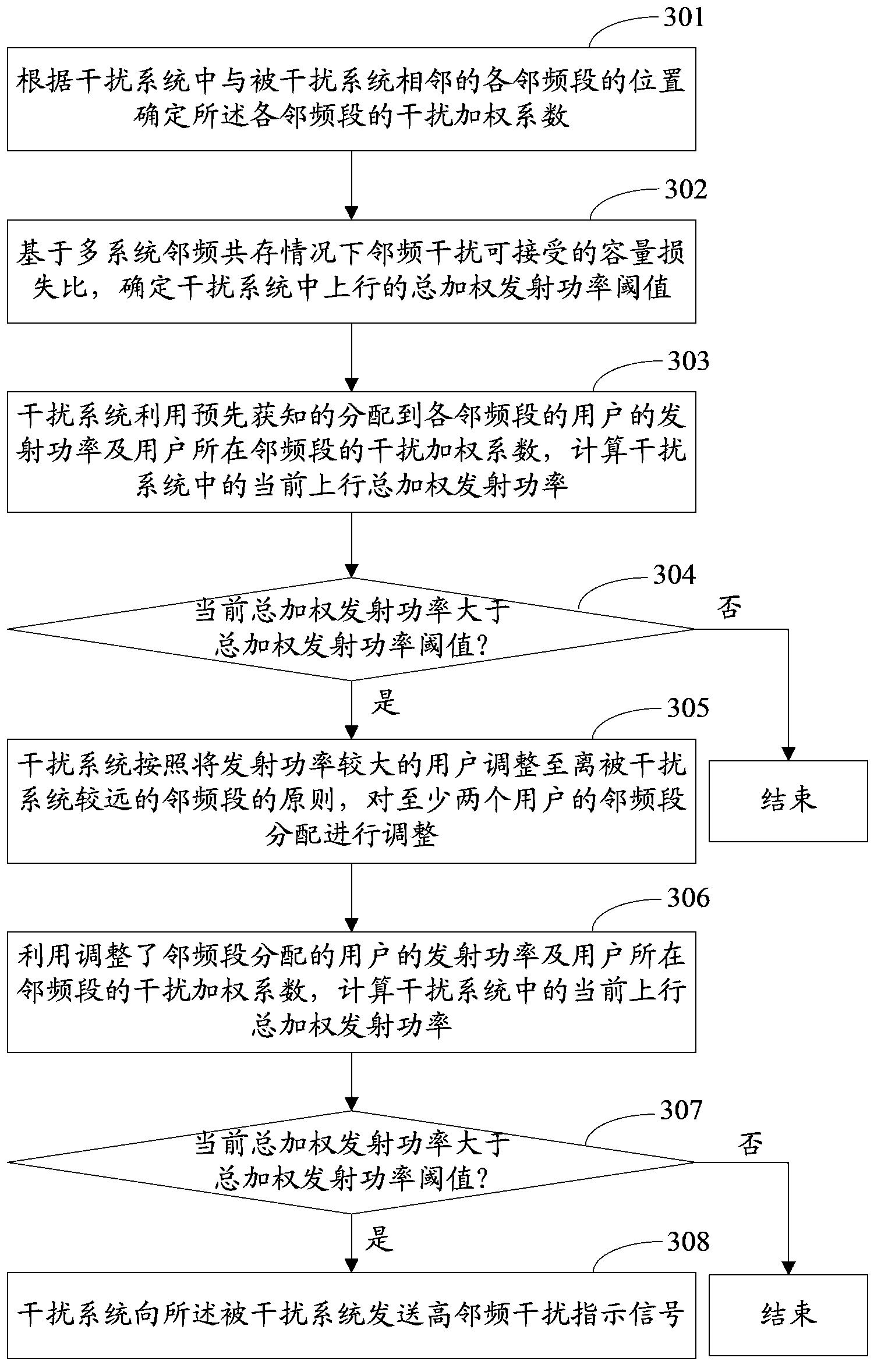
[0068] image 3 It is a flow structure diagram of the interference indication method under adjacent frequency coexistence in the second embodiment of the present invention. Such as image 3 As shown, the method may include the following processing flow.

[0069] Step 301: Determine the interference weighting coefficient of each adjacent frequency band according to the position of each adjacent frequency band adjacent to the interfered system in the interference system.

[0070] Among them, the adjacent frequency band closer to the interfered system in the interfering system has a larger weight value, and the adjacent frequency band farther from the interfered system has a smaller weight v...


PUM


Abstract

The invention discloses an interference indication method and device under an adjacent channel coexisting condition. The method comprises the following steps: determining adjacent channel bands adjacent to an interfered system in an interference system, and calculating current total transmission power of an uplink in the interference system according to previously obtained user transmission power distributed to the adjacent channel bands by the interference system; judging whether the current total transmission power is more than a preset total transmission power threshold, if so, sending a high adjacent channel interference indication signal to the interfered system. According to the technical scheme disclosed by the invention, the adjacent channel interference between systems can be indicated.

Description

Technical field [0001] This application relates to wireless communication technology, in particular to a method and device for indicating interference under adjacent frequency coexistence. Background technique [0002] In order to meet the challenges of broadband access technology and to meet the needs of new services, the International Organization for Standardization 3GPP launched its long-term evolution technology (LTE: Long Term Evolution) standardization work at the end of 2004. It is the largest new technology research and development project launched by 3GPP in the past two years. The research of LTE includes the reduction of delay, higher user data rate, improvement of system capacity and coverage, and reduction of operating cost. The main performance goals of the 3GPP LTE project include: being able to provide a much higher peak rate than the 3G system; improving the performance of cell edge users; increasing cell capacity; reducing system delay and shortening the migra...

Claims


Application Information

Patent Timeline
Patent Type & Authority Applications(China)
IPC IPC(8): H04W16/14H04W72/08H04W72/54
Inventor 兰洋原田笃
Owner NTT DOCOMO INC
Why Eureka
Try Eureka