Paying-off device

A technology of pay-off device and wire area, applied in the field of pay-off device, can solve the problems of cumbersome operation, heavy workload, large space, etc., achieve the effect of reducing space occupation, reducing labor intensity and improving work efficiency

Active Publication Date: 2014-04-02
CRRC TANGSHAN CO LTD
View PDF4 Cites 2 Cited by
  • Summary
  • Abstract
  • Description
  • Claims
  • Application Information

AI Technical Summary

Problems solved by technology

This form of placing two pay-off devices requires a large space and cannot be used in places with insufficient space
Moreover, the method of reconnecting the thread after two thread trimmings is cumbersome to operate, and the workload is large, which reduces labor efficiency.

Method used


Image

  • Paying-off device
  • Paying-off device
  • Paying-off device

Examples


Embodiment Construction

[0022] In order to make the purpose, technical solutions and advantages of the invention more clear, the technical solutions in the embodiments of the invention will be clearly and completely described below in conjunction with the drawings in the embodiments of the invention. Obviously, the described embodiments are Invention type some embodiments, but not all embodiments.

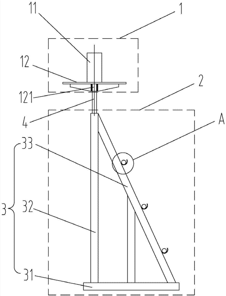
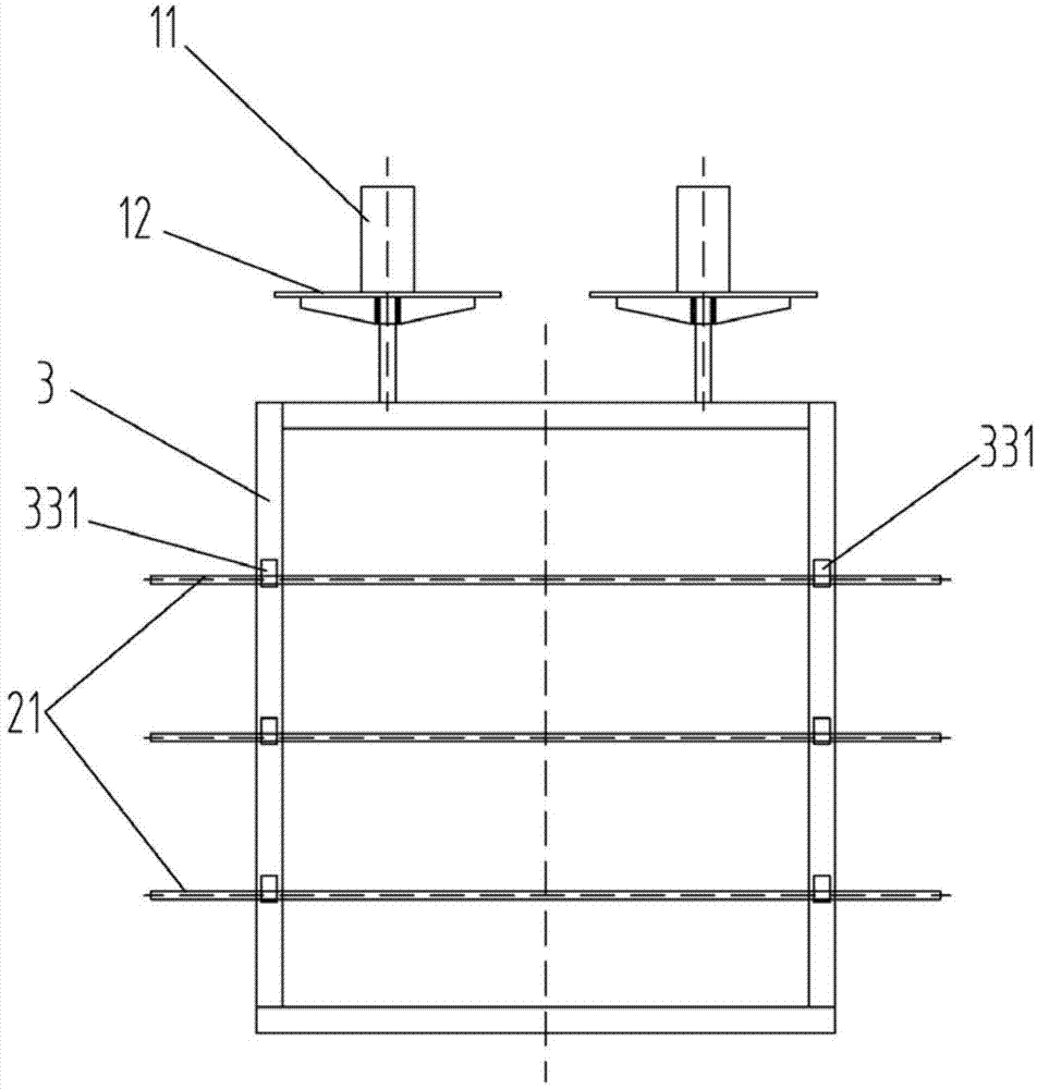
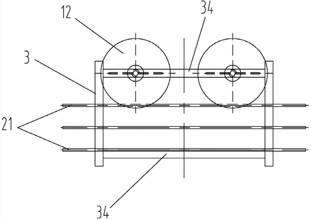
[0023] figure 1 For the side view of the pay-off device of the embodiment of the present invention, please refer to figure 1 . The wire pay-off device of the present invention includes a support frame 3 on which at least two wire pay-off areas are arranged. In this embodiment, there are two wire-discharging areas, namely the first wire-discharging area 1 and the second wire-discharging area 2 . Since the pay-off device of the present invention is provided with at least two pay-off areas on the same support, the space occupation of the pay-off device is greatly reduced and the cost is saved. At the sam...


PUM


Abstract

The invention provides a paying-off device and belongs to the field of wire arrangement and control of rail trains. The paying-off device comprises a supporting frame, wherein the supporting frame is provided with at least two paying-off regions. Due to the fact that multiple paying-off regions are arranged on the same support of the paying-off device, the space occupied by the paying-off device is greatly decreased, and the cost is saved. In addition, the paying-off device can greatly reduce the labor intensity and improve the working efficiency.

Description

technical field [0001] The invention relates to the field of wiring control of rail trains, in particular to a wire releasing device. Background technique [0002] The cable wiring on rail trains is usually in the form of overall packaging when it is not deployed on the train. Some cable wiring uses a relatively small quantity and is packaged in the form of coiled wires. Some single-core wiring uses a relatively large quantity and is packaged in the form of axis. Usually the cable wiring length of the overall package is relatively long, which is not suitable for direct deployment and control on the train. It is necessary to cut the cable wiring into different lengths according to different needs before using it on the train. [0003] In the process of cable wiring trimming, due to the large number of cable wiring, it is usually necessary to cooperate with the wire releaser to cut the cable wiring. For the overall trimming of a wire harness composed of different types of wi...

Claims


Application Information

Patent Timeline
Patent Type & Authority Applications(China)
IPC IPC(8): B65H49/18
Inventor 赵丽娜崔虎山黄少东苏伟玥冯艳双
Owner CRRC TANGSHAN CO LTD
Why Eureka
Try Eureka