Automatically tested decoding board and test method thereof

An automated testing and decoding board technology, applied in electronic circuit testing, the layout of structural components in carrier equipment, etc., can solve problems such as the inability to standardize detection of DVD decoding boards, and achieve the effect of improving test efficiency

Inactive Publication Date: 2014-04-02
深圳市隆科电子有限公司
View PDF3 Cites 2 Cited by
  • Summary
  • Abstract
  • Description
  • Claims
  • Application Information

AI Technical Summary

Problems solved by technology

Therefore, it is impossible to do a comprehensive

Method used


Image

  • Automatically tested decoding board and test method thereof

Examples


Embodiment Construction

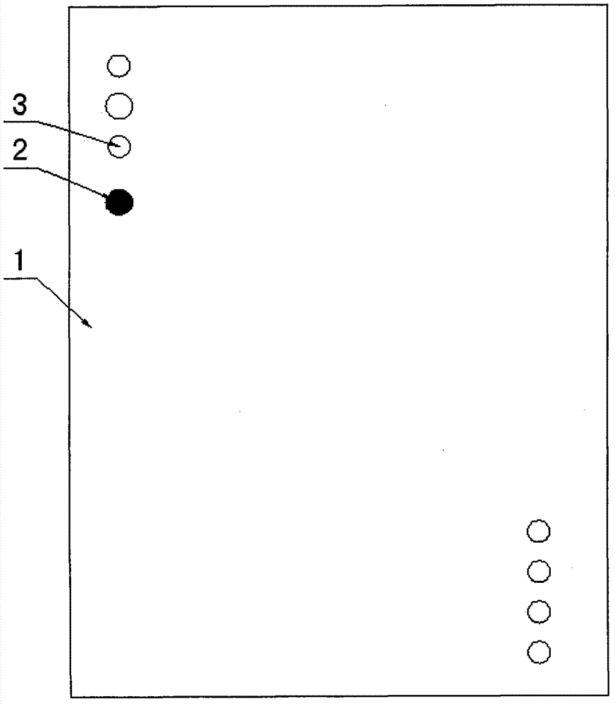
[0012] Such as figure 1 As shown, a kind of automated test decoding board of the present invention includes a PCB board 1 as a carrier, a printed circuit is arranged on the front side of the PCB board 1, and electrical components for execution are also installed on the PCB board 1, and the PCB board 1 The reverse side of the board 1 is provided with more than one via hole 3, the copper foil 2 is welded in the via hole 3, and the copper foil 2 protrudes from the PCB board 1, which is convenient for detection, and the PCB board 1 around the copper foil is Also marked with silk screen.

[0013] In a preferred mode of the present invention, the via hole is facing the printed circuit on the front side of the PCB 1 .

[0014] In a preferred manner of the present invention, the copper foil is connected to the printed circuit on the front surface of the PCB 1 .

[0015] In a preferred manner of the present invention, the copper foil 2 on the one via hole 3 is a test point.

[0016]...


PUM


Abstract

The invention discloses an automatically tested decoding board. The automatically tested decoding board comprises a PCB (printed circuit board) serving as a carrier, wherein a printed circuit is arranged on the front surface of the PCB; an electrical element used for execution is also arranged on the PCB; more than one through hole is formed in the back surface of the PCB; a copper foil is welded in each through hole and protrudes from the PCB, so that detection is facilitated; silk screens are also marked on the PCB on the periphery of the copper foil; test instruments, such as an oscilloscope or a universal meter, can in directly contact with a test signal point on the back surface of the PCB during test; the signal value required to be tested can be known without contrasting PCB circuit drawings or a schematic diagram of the decoding board; the circuits of all signal test point are not influenced mutually, external interference is also avoided, and the test efficiency of working staff is greatly improved; the data signal can also be measured through identifying the silk screens of the signal test point on the back surface of the PCB even by a non-professional tester without understanding the PCB circuit of a DVD (digital video disk) decoding board.

Description

technical field [0001] The invention relates to the field of DVD accessories, in particular to an automatic test decoder board and a test method thereof. Background technique [0002] Common DVD decoding boards produced by major manufacturers have not been able to develop the design of the test signal point on the back of the PCB. It mainly adopts manual detection of DVD decoder board. The signal points of the test are based on the function slots supported by the decoder board, and the test parameters are based on voltage reference. The quality inspection of DVD decoder board mainly uses a series of measuring instruments such as multimeter and oscilloscope and the working experience of testers. Only professional testers can correctly understand the circuit principle of DVD decoder board and the electrical performance parameters of each test point, and Due to the highly integrated circuit, the test points and data reference values ​​of each decoding board are quite different...

Claims


Application Information

Patent Timeline
IPC IPC(8): G11B33/12G01R31/28
Inventor 徐琛夏小军
Owner 深圳市隆科电子有限公司
Why Eureka
Try Eureka