
Pressure head of valve oil seal

A valve oil seal and oil seal technology, which is applied in metal processing, metal processing equipment, manufacturing tools, etc., can solve the problems of inaccurate positioning and guidance of the guide shaft, inability to tightly wrap the valve oil seal, and inaccurate positioning of the valve oil seal. The effect of press-fitting accuracy and success rate

Inactive Publication Date: 2014-04-09
GUANGXI YUCHAI MASCH CO LTD
View PDF0 Cites 2 Cited by
  • Summary
  • Abstract
  • Description
  • Claims
  • Application Information

AI Technical Summary

Problems solved by technology

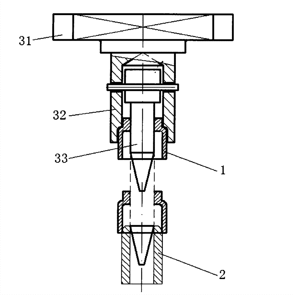
[0004] However, the floating connection between the guide shaft and the pin of the oil seal pressure sleeve, on the one hand, makes the guide shaft easy to insert into the valve guide to play a guiding role, but on the other hand, makes the guide shaft deviate from the vertical direction, so that the downward pressure of the press machine produces a lateral component force , causing the valve oil seal to deflect
In addition, the diameter of the guide shaft is too small compared with the inner hole of the valve guide, so that the positioning of the guide shaft is not accurate
And the length of the guide shaft protruding from the oil seal gland is too short, so that when the guide shaft is not introduced into the valve guide hole, the front end of the valve oil seal has touched the valve guide, resulting in inaccurate positioning and the valve oil seal is easily crushed
Finally, the side wall of the large mouth of the stepped port at the lower end of the oil seal gland is too short to tightly cover the entire valve oil seal, which makes the positioning of the valve oil seal itself on the oil seal pressure head inaccurate during the press-fitting process, resulting in improper press-fitting. low success rate

Method used


Image

  • Pressure head of valve oil seal
  • Pressure head of valve oil seal
  • Pressure head of valve oil seal

Examples


Embodiment Construction

[0021] A specific embodiment of the present invention will be described in detail below in conjunction with the accompanying drawings, but it should be understood that the protection scope of the present invention is not limited by the specific embodiment. It should be understood that the "upper", "lower", "left", "right", "front" and "reverse" mentioned in the following embodiments of the present invention are all based on the directions shown in the drawings , These words used to limit directions are only for convenience of description, and do not represent limitations on the specific technical solutions of the present invention.

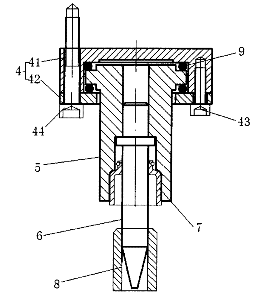
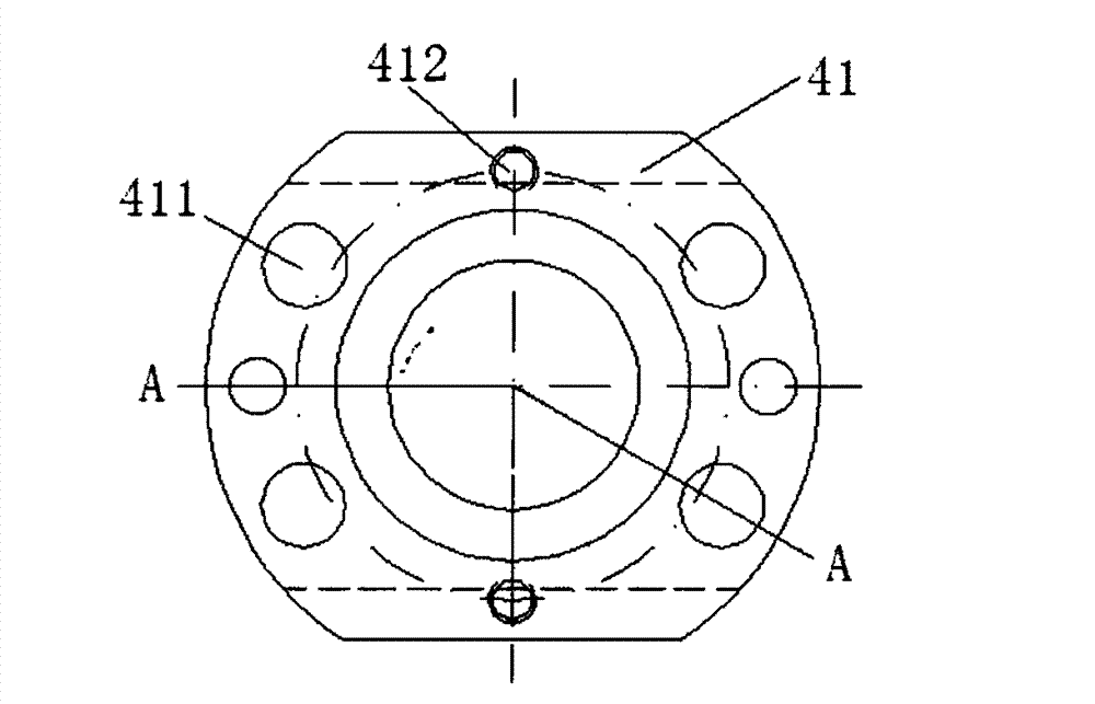
[0022] Such as figure 2 As shown, the valve oil seal pressure head of the present invention includes: a base (4), an oil seal pressure sleeve (5) and a guide shaft (6). Wherein, the base (4) includes: an upper shell (41) and a lower cover (42) that are fastened to each other, such as Figure 3 to Figure 5 As shown, the upper shell (41) is an in...


PUM


Abstract

The invention discloses a pressure head of a valve oil seal. The pressure head of the valve oil seal comprises a base, an oil seal pressing sleeve and a guide shaft. An upper shell and a lower cover of the base are fastened with each other to form a connecting cavity, the oil seal pressing sleeve is tubular, the upper end of the oil seal pressing sleeve is arranged in the connecting cavity and is connected with the connecting cavity in a ball suspension manner, and a lower port of the oil seal pressing sleeve is matched with the valve oil seal to be subjected to press-fitting; the guide shaft is cylindrical and is inserted into the oil seal pressing sleeve, and a tapered guide head is arranged at the lower end of the guide shaft. The pressure head of the valve oil seal has the advantages that the oil seal pressing sleeve of the pressure head of the valve oil seal is connected with the base in the ball suspension manner, so that the oil seal pressing sleeve and the guide shaft can keep in perpendicular directions while the oil seal pressing sleeve and the guide shaft can be finely repositioned in the left-right directions on ball planes, press-fitting guiding and positioning can be conveniently carried out by the guide shaft when a valve guide pipe is not aligned with the pressure head of the valve oil seal, the press-fitting precision can be improved, and a press-fitting success rate can be increased.

Description

technical field [0001] The invention relates to the field of engines, in particular to a valve oil seal pressure head. Background technique [0002] Such as figure 1 As shown, when the cylinder head is assembled, the valve oil seal needs to be press-fitted on the valve guide through the oil seal pressure head connected with the press-fitting machine. The existing oil seal pressure head includes: a base connected with a press machine, an oil seal pressure sleeve and a guide shaft. Among them, the oil seal pressing sleeve is in the shape of an inverted cylinder, the top is fixed on the base, the side wall of the middle part is oppositely provided with pin holes, and the bottom port is a stepped port for matching with the valve oil seal to be pressed. The guide shaft is a stepped shaft structure, the upper large shaft is inserted into the inner cavity of the inverted cylindrical oil seal gland, and fixed through the pins; the lower end of the small shaft has a tapered guide h...

Claims


Application Information

Patent Timeline
Patent Type & Authority Applications(China)
IPC IPC(8): B23P19/02
CPCB23P19/02
Inventor 汪明张健朱岩秦川王俊蛟龚文斌刘星唐国盛粟荣锦
Owner GUANGXI YUCHAI MASCH CO LTD
Learn More