Mechanical press mounting structure of group large-power flat-plate power electronic device

A technology for power electronic devices and press-fit structures, which is applied in the field of mechanical press-fit structures of grouped high-power flat-panel power electronic devices, can solve the problems of increased thermal resistance of conductive contact surfaces, unfavorable heat dissipation, uncontrolled, etc., and eliminates the need for Assembly error, easy maintenance and replacement, the effect of constant pressure

Active Publication Date: 2010-08-04
TIANJIN RES INST OF ELECTRIC SCI +1
View PDF2 Cites 3 Cited by
  • Summary
  • Abstract
  • Description
  • Claims
  • Application Information

AI Technical Summary

Problems solved by technology

If the press-fitting force is too small, the thermal resistance of the conductive contact surface of the flat power electronic device will increase, which is not conducive to heat dissipation; in addition, the contact inside the device such as the control electrode may also be in a bad state, and it is likely to be out of control.
If the pressing force is too large, the flat power electronic device may be directly damaged

Method used


Image

  • Mechanical press mounting structure of group large-power flat-plate power electronic device
  • Mechanical press mounting structure of group large-power flat-plate power electronic device
  • Mechanical press mounting structure of group large-power flat-plate power electronic device

Examples


Embodiment Construction

[0021] The embodiments of the present invention will be further described below in conjunction with the accompanying drawings; it should be noted that: this embodiment is descriptive, not restrictive, and cannot be used to limit the protection scope of the present invention.

[0022] This embodiment is described by taking the IGCT power unit string as an example.

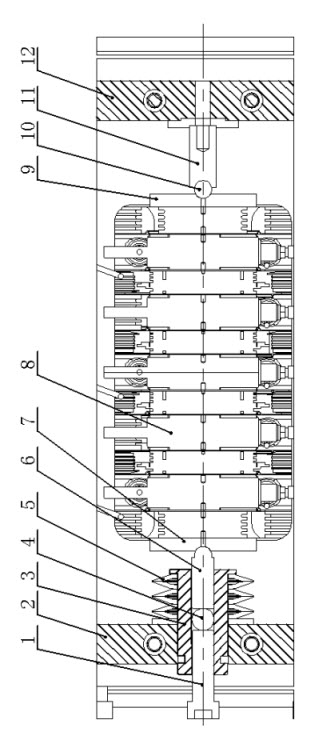
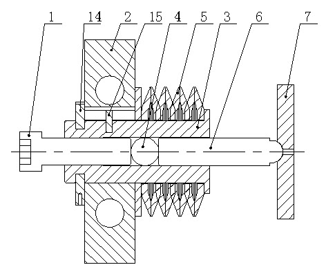
[0023] A group of high-power flat-plate type power electronic device mechanical press-fit structure, which is composed of a left support plate 2, a right support plate 12, a left ejector rod 6, a right ejector rod 11, a left pressure plate 7, and a right pressure plate 9. The power device string 8 is installed horizontally and coaxially between the right pressure plate. The top is installed on the left and right pressure plates. Innovation point of the present invention is:

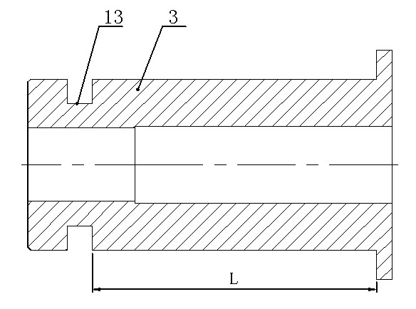
[0024] (1) The left ejector rod is coaxially slidably installed in a spring mandrel 3, and the spring mandrel passes through its radially in...


PUM


Abstract

The invention relates to a mechanical press mounting structure of a group large-power flat-plate power electronic device, which is technically characterized in that firstly, a left ejector pin is coaxially installed in a spring mandrel in a sliding mode, the spring mandrel is installed on a left support plate through a key pin which is mounted along the radial direction of the spring mandrel, a set of disk springs is mounted on the spring mandrel at the right end of the support plate, an annular groove is radially manufactured on the spring mandrel at the right end of the support plate, and a limiting chuck is mounted in the annular groove; secondly, a press mounting screw is coaxially engaged in the spring mandrel at the left side of the left ejector pin; and thirdly, the right end of the left ejector pin and a left pressure plate are in spherical pair installation, and the left end of the a right ejector pin and a right pressure plate are in spherical pair installation. In the mechanical press mounting structure, the disk springs are adopted as driving elements, the compression stroke of the disk springs are accurately controlled through machining parts and has nothing to do with the assembly precision; the mechanical pressing force is accurately controlled with constant pressure; and the structure has large latitude for the assembly length of power device series, eliminates the assembling clearance, has self-adaption for the length of the power device series in a certain range, and has high press mounting precision.

Description

technical field [0001] The invention relates to the press-fitting of electronic devices, in particular to a mechanical press-fitting structure of grouped high-power flat-plate power electronic devices. Background technique [0002] Power electronic devices are the main devices that constitute the main circuit of power electronic conversion systems (such as frequency converters, power grid dynamic compensators, etc.). High-power planar power electronic devices can only work normally after the pressure specified in the technical data is applied to the anode and cathode surfaces by external force. [0003] The press-fitting of a single flat-panel power electronic device is relatively simple. Generally, its two planes are in direct contact with two radiators, and then spring steel (or spring washers) and some bolts are added to the two radiators, and the bolts are fastened. It is sufficient to apply a specified pressure along the axial direction of the flat power electronic dev...

Claims


Application Information

Patent Timeline
Patent Type & Authority Applications(China)
IPC IPC(8): H01L25/04H01L23/13H01L25/07
Inventor 蔡维徐道恒高树瑞楚子林王建峰刘国林赵相宾
Owner TIANJIN RES INST OF ELECTRIC SCI
Why Eureka
Try Eureka