
Turning belt side-pulling track mechanism

A belt and track technology, applied in the field of turning belt side pull track mechanism, can solve the problems of inability to perform high-speed rotation, transported items deviating from the track, rotating centripetal force decomposition, etc., to solve the problem of belt deviation, easy to use, and easy to install.

Inactive Publication Date: 2014-04-09
倪娉娉
View PDF6 Cites 0 Cited by
  • Summary
  • Abstract
  • Description
  • Claims
  • Application Information

AI Technical Summary

Problems solved by technology

[0002] The turning track mechanism in the prior art basically adopts a trough track mechanism. In the turning position, the transported goods often deviate from the track. The main reason is that the track itself cannot decompose the rotational centripetal force when turning. , can be decomposed by the friction between the object itself and the rotating belt, and high-speed rotation cannot be performed, because at high speeds, the orbit itself will deviate from the orbit due to the low rotational centripetal force, especially when increasing the speed, all The rotational centripetal force is distributed on the rotating belt, and the rotational centripetal force that cannot be decomposed will make the rotating belt quickly run off the track. How to internally decompose the rotational centripetal force?

Method used


Image

  • Turning belt side-pulling track mechanism

Examples


Embodiment Construction

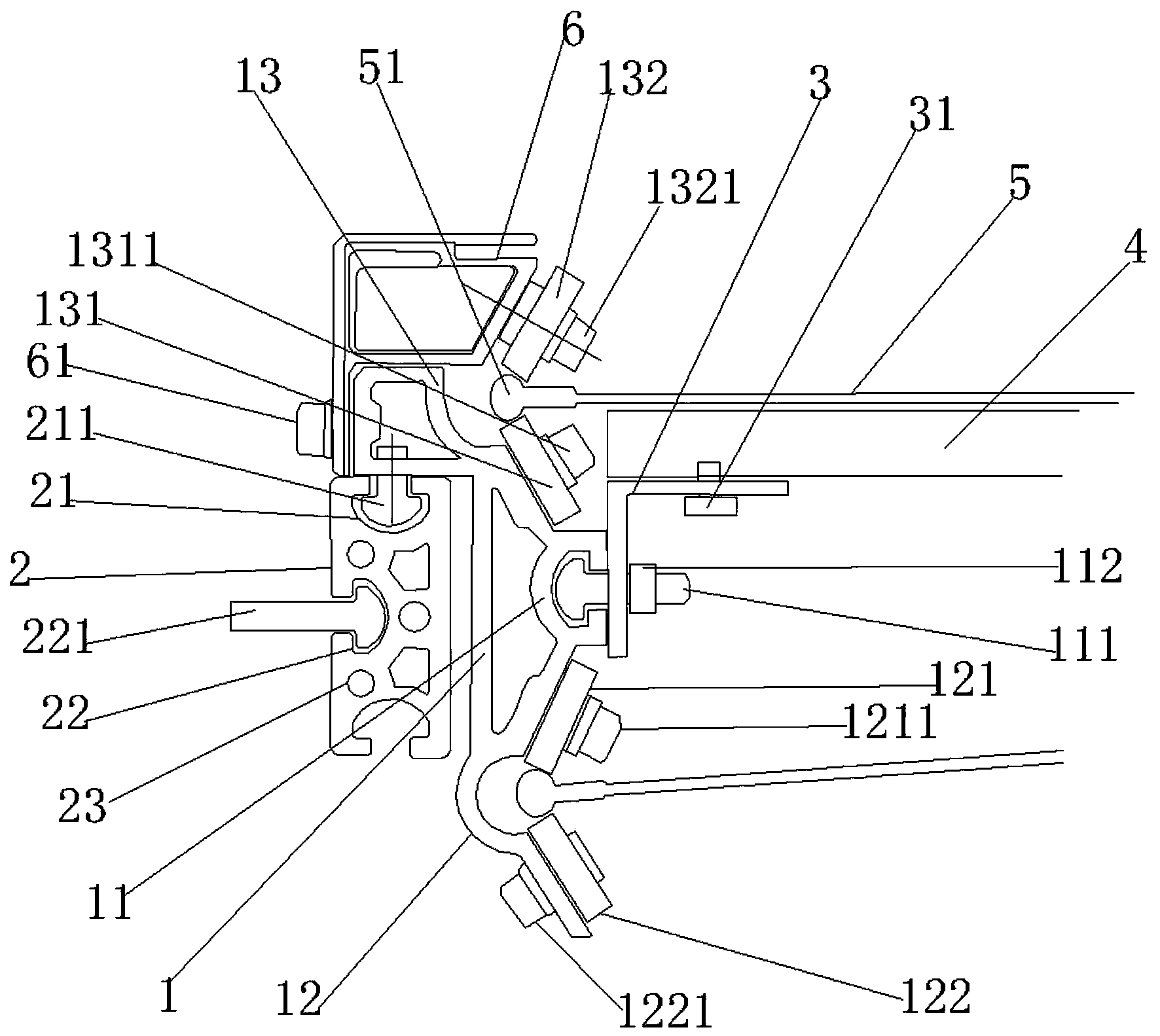
[0018] Such as figure 1As shown, a turning belt side pull track mechanism includes a triangular support block 1, and the right side of the triangular support block 1 is provided with an inner bolt fixing groove 11, and the inner bolt fixing groove 11 is provided with an inner bolt 111. The inner bolt 111 is provided with an inner bolt lock nut 112, the lower side of the triangular support block 1 is fixedly provided with a lower track groove 12, the upper side of the triangular support block 1 is fixedly provided with an upper track groove 13, and the lower side of the triangular support block 1 is fixedly provided with an upper track groove 13, and the lower side of the triangular support block 1 The side is provided with an installation connection block 2, and the right side of the triangular support block 1 is provided with a belt plate support frame 3, and the belt plate support frame 3 is fixed on the triangular support block 1 by inner bolts 111, and on the belt plate sup...


PUM


Abstract

The invention provides a turning belt side-pulling track mechanism. The turning belt side-pulling track mechanism comprises a triangular supporting block. An internal bolt fixing groove is formed in the right side of the triangular supporting block. An internal bolt is arranged in the internal bolt fixing groove. An internal bolt locknut is arranged on the internal bolt. A lower track trough is fixedly arranged on the lower side of the triangular supporting block. An upper track trough is fixedly arranged on the upper side of the triangular supporting block. An installing and connecting block is arranged on the lower side of the triangular supporting block. A belt plate supporting frame is arranged on the right side of the triangular supporting block. The belt plate supporting frame is fixed to the triangular supporting block through the internal bolt. The belt plate supporting frame is provided with a belt plate which is fixed to the belt plate supporting frame through a belt plate fixing bolt. The belt plate is provided with a rotary belt. An upper wheel fixing block is arranged on the upper portion of the left side of the triangular supporting block and fixed to the triangular supporting block through a fixing block bolt. The turning belt side-pulling track mechanism has the advantages that the turning belt side-pulling track mechanism is reasonable in design, simple in structure and convenient to use; rotation centripetal force is resolved through a rotating, supporting and connecting mechanism while the inclination angle of the overall mechanism is adjusted.

Description

technical field [0001] The invention relates to the field of turning track mechanisms, in particular to a turning belt side pulling track mechanism. Background technique [0002] The turning track mechanism in the prior art basically adopts a trough track mechanism. In the turning position, the transported goods often deviate from the track. The main reason is that the track itself cannot decompose the rotational centripetal force when turning. , can be decomposed by the friction between the object itself and the rotating belt, and high-speed rotation cannot be performed, because at high speeds, the orbit itself will deviate from the orbit due to the low rotational centripetal force, especially when increasing the speed, all The rotational centripetal force is distributed on the rotating belt, and the rotational centripetal force that cannot be decomposed will make the rotating belt quickly run off the track. How to internally decompose the rotational centripetal force? ...

Claims


Application Information

Patent Timeline
IPC IPC(8): B65G21/20
Inventor 倪娉娉
Owner 倪娉娉
Learn More