
Counter-force system for rectangular shield tunneling

A rectangular shield and shield technology, applied in mining equipment, earthwork drilling, tunnels, etc., can solve the problems of uncertain force on the steel ring, potential safety hazards, and occupation of lifting space for construction materials, so as to increase the transportation space, The effect of reducing the number and stabilizing the structure

Inactive Publication Date: 2014-04-09
SHANGHAI MECHANIZED CONSTR GRP
View PDF3 Cites 3 Cited by
  • Summary
  • Abstract
  • Description
  • Claims
  • Application Information

AI Technical Summary

Problems solved by technology

[0003] In the construction of rectangular shield, if the steel ring and steel support are still installed on the upper part of the open negative ring according to the conventional method, on the one hand, due to the different starting conditions of the shield each time, the connection position of the steel support and the steel ring is different, resulting in The force of the steel ring is uncertain, which brings difficulties to the design of the steel ring. On the other hand, because some steel supports need to be set as oblique supports, the length of the oblique steel supports varies with each connection position, resulting in steel The support needs to be processed each time, or when the length of the steel support is insufficient, a steel plate is added behind the steel support, which will cause certain safety hazards to the construction of the shield hole. Moreover, since multiple steel supports are set on the upper part of the negative ring of the opening, It also occupies part of the construction material lifting space

Method used


Image

  • Counter-force system for rectangular shield tunneling

Examples


Embodiment Construction

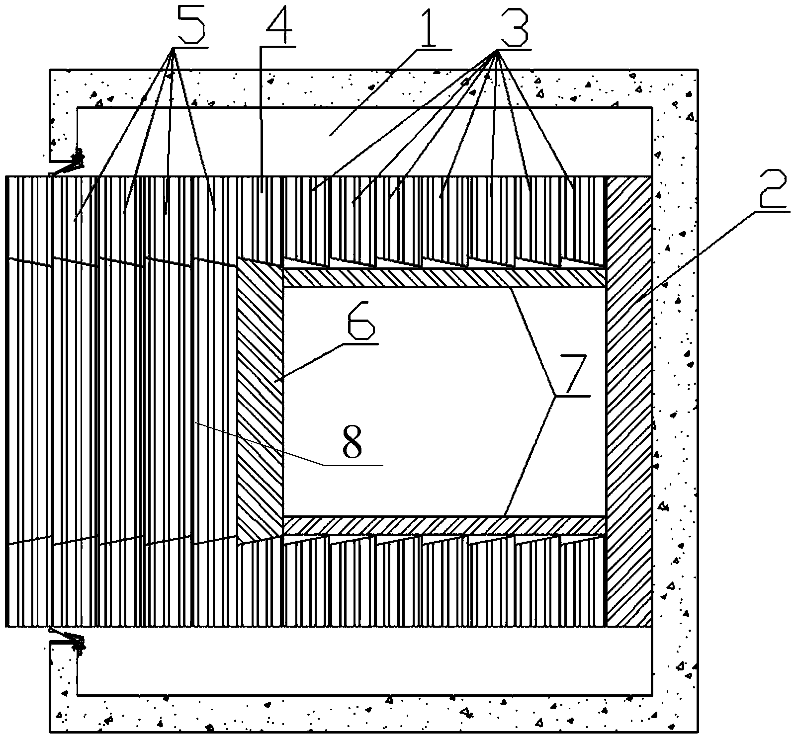
[0011] The following will combine figure 1 A detailed description of the reaction force system for rectangular shield tunneling provided by the present invention, which is an optional embodiment of the present invention, can be considered by those skilled in the art without changing the spirit and content of the present invention. Revise and polish it.

[0012] Please refer to figure 1 , this embodiment provides a reaction force system for rectangular shield tunneling, which is set in the originating shaft 1 and includes a reaction force frame 2, an open negative ring 3, a closed negative ring system and a steel beam 7. The reaction force frame 2, the open negative ring 3 and the closed negative ring system are sequentially connected along the direction of shield tunneling, and the reaction force frame 2 is fixed on the opening of the launch shaft 1 opposite to the opening of the launch shaft On the side wall, the closed negative ring system passes through the opening of the...


PUM


Abstract

The invention provides a counter-force system for rectangular shield tunneling. The counter-force system is arranged inside an original well and comprises a counter-force frame, an opened negative ring, a closed negative ring system and a steel beam, wherein the counter-force frame, the opened negative ring and the closed negative ring system are connected in sequence in the direction of shield tunneling, the counter-force frame is fixedly arranged on the side wall of the original well, opposite to the opening of the original well, the closed negative ring system penetrates through the opening of the original well, the steel beam is located on the inner side of the opened negative ring, and the two ends of the steel beam are connected with the closed negative ring system and the counter-force frame respectively. Due to the introduction of the unique closed negative ring system and steel beam, the whole system is clearly stressed, the structure is more stable, and the steel beam does not need to be machined every time to meet the length demand; meanwhile, due to the fact that the number of counter-force steel supports is reduced, the allocation and transportation space of construction materials is increased. The counter-force system suitable for the rectangular shield tunneling is provided.

Description

technical field [0001] The invention relates to an improvement of a shield tunneling construction, in particular to a reaction force system for a rectangular shield tunneling. Background technique [0002] During the construction of shield tunneling, part of the negative ring segment in the initial working shaft usually needs to be set as an open negative ring for lifting construction materials and equipment, and a steel ring and 4 steel supports are installed on the upper part of the open negative ring to transfer Reaction force. [0003] In the construction of rectangular shield, if the steel ring and steel support are still installed on the upper part of the open negative ring according to the conventional method, on the one hand, due to the different starting conditions of the shield each time, the connection position of the steel support and the steel ring is different, resulting in The force of the steel ring is uncertain, which brings difficulties to the design of th...

Claims


Application Information

Patent Timeline
Patent Type & Authority Applications(China)
IPC IPC(8): E21D9/06
Inventor 吴欣之罗鑫林济姜小强朱德坤王国弼金中林过浩侃裘水根
Owner SHANGHAI MECHANIZED CONSTR GRP
Learn More