A construction method for supporting with prestressed h-shaped steel support structure

A technology of supporting structure and construction method, which is applied in basic structure engineering, excavation, construction, etc., can solve the problems of non-recyclable supporting process, poor stability of deep foundation pit supporting structure, inconvenient operation, etc. The effect of improving support strength and saving costs

Active Publication Date: 2017-03-29
JIANGSU DONGHENAN GEOTECHNICAL TECH CO LTD
View PDF4 Cites 0 Cited by
  • Summary
  • Abstract
  • Description
  • Claims
  • Application Information

AI Technical Summary

Problems solved by technology

[0007] The purpose of the present invention is to provide a construction method using a prestressed H-shaped steel support structure to solve the technical problems in the prior art that the support structure of deep foundation pits is poor in stability, cannot be recycled and reused, and the support process is cumbersome and inconvenient to operate.

Method used


Image

  • A construction method for supporting with prestressed h-shaped steel support structure
  • A construction method for supporting with prestressed h-shaped steel support structure
  • A construction method for supporting with prestressed h-shaped steel support structure

Examples


Embodiment 1

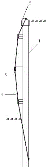
[0052] Determine the length of support pile 1, the number of steel supports 3, the length of steel supports 3 and the adjacent steel supports on each prestressed support unit according to the geological data of the foundation pit to be excavated, the design depth and the surrounding environmental conditions The distance between the seat 3 is to anchor one end of the prestressed tendon 4 to the lower part of the support pile 1, and the other end of the prestressed tendon passes through the limit devices 5 on all steel supports 3 in turn to prefabricate the prestressed support unit.

[0053] Such as figure 1 As shown, the length of the support pile 1 is 15m, the excavation depth of the foundation pit is 10m, and the distance between adjacent support piles 1 is 1.6m, and each support pile 1 is provided with three steel supports 3, each support The maximum distance between adjacent steel supports 3 on the retaining pile 1 is 3m, the minimum is 1m, the longest steel support 3 is 0....

Embodiment 2

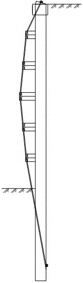
[0055] Such as Figure 4 Shown, the length of described support pile 1 is 18m, and foundation pit excavation depth is 12m, and adjacent support pile 1 spacing is 1.2m and is provided with five steel supports 3 on each support pile 1, each support The maximum distance between adjacent steel supports 3 on the retaining pile 1 is 3m, the minimum is 1m, the longest steel support 3 is 0.7m in length, and each prestressed support unit is provided with four prestressed prestressed Rib 4, the nominal diameter of each prestressed prestressed tendon 4 is 15.2mm, and the support pile 1 is 6m deep below the bottom of the pit.

Embodiment 3

[0057] Such as Figure 5 As shown, the length of the support pile 1 is 30m, the excavation depth of the foundation pit is 15m, the distance between adjacent support piles 1 is 0.8m, and each support pile 1 is provided with seven steel supports 3, each The maximum distance between adjacent steel supports 3 on the support pile 1 is 3m, the minimum is 1m, the longest steel support 3 is 0.9m in length, and each prestressed support unit is provided with five prestressed prestressed Stress tendons 4, the nominal diameter of each prestressed prestressed tendons 4 is 15.2mm, and the support pile 1 is 15m deep below the bottom of the pit.


PUM


Abstract

The invention discloses a prestressed H-type steel supporting structure and a construction method thereof. The prestressed H-type steel supporting structure comprises a plurality of prestressed supporting units. Each prestressed supporting unit comprises a supporting pile, a plurality of steel supports and prestressed bars, wherein the supporting pile is vertically arranged on one side of a foundation pit to be excavated, the steel supports are arranged on the supporting pile from top to bottom, and one end of each prestressed bar is anchored to the lower portion of the supporting pile. The prestressed supporting units are sequentially driven into the periphery of the foundation pit to be excavated, the steel supports all face the foundation pit to be excavated, a top beam is arranged at the top end of each prestressed supporting unit, and each prestressed supporting unit and the corresponding top beam are integrated. Tensile force is applied to the prestressed bars, and the upper ends of the prestressed bars are anchored to the top beams. The horizontal component of the tensile force borne by the prestressed bars is transferred to the supporting structure, and therefore partial soil pressure of soil is counteracted, the supporting strength is improved, and deformation of the supporting piles is reduced. In addition, the supporting structure can be recycled, and therefore the cost is reduced.

Description

technical field [0001] The invention belongs to the field of construction, and in particular relates to a construction method for supporting with a prestressed H-shaped steel supporting structure. Background technique [0002] When protecting deep foundation pits, the existing retaining piles usually adopt bored piles or immersed pipe piles, and all of them adopt the construction method of pouring on site. For example, the application number 201420330061.X, the invention name is the utility model patent of cast-in-place external prestressed steel pipe concrete pile and supporting pile wall, which includes steel pipes, concrete layers cast in-situ inside the steel pipes and set on the steel pipes. A plurality of prestressed tendons on the steel pipe, the prestressed tendons are arranged along the axial direction of the steel pipe, including a top section, a middle section and a bottom section, the middle section is located outside the steel pipe, and the top section and the b...

Claims


Application Information

Patent Timeline
Patent Type & Authority Patents(China)
IPC IPC(8): E02D17/04
Inventor 王建兰李仁民
Owner JIANGSU DONGHENAN GEOTECHNICAL TECH CO LTD
Why Eureka
Try Eureka