
Air intake for internal combustion engines

An air intake device, internal combustion engine technology, applied in the direction of internal combustion piston engine, combustion engine, mechanical equipment, etc., can solve problems such as crankshaft noise, and achieve the effect of optimizing combustion efficiency

Active Publication Date: 2016-04-20
HONDA MOTOR CO LTD
View PDF4 Cites 0 Cited by
  • Summary
  • Abstract
  • Description
  • Claims
  • Application Information

AI Technical Summary

Problems solved by technology

[0008] However, in the medium to high load range of the internal combustion engine, if the swirl flow of the tumble flow is too strong, crankshaft noise may be generated due to rapid combustion
[0009] Therefore, in the medium-to-high load range, it is desired to suppress the intake air flowing in the upper passage of the intake port, but in the intake control performed by the intake control valve of Patent Document 1, it is not possible to close the upper passage only partially. The upstream side of the opening to suppress the intake air flowing in the upper passage

Method used


Image

  • Air intake for internal combustion engines
  • Air intake for internal combustion engines
  • Air intake for internal combustion engines

Examples


Embodiment Construction

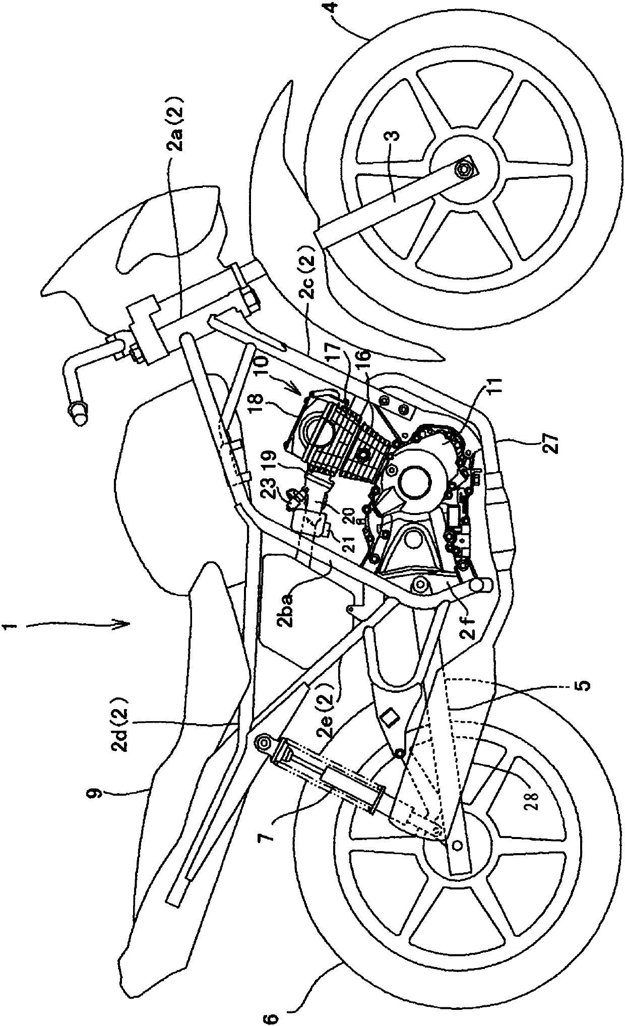
[0049] Below, based on Figure 1 to Figure 13 An embodiment of the present invention will be described.

[0050] figure 1 It is an overall side view of the two-wheeled motor vehicle 1 equipped with the internal combustion engine 10 of this embodiment.

[0051] The frame 2 of the two-wheeled motor vehicle 1 has a pair of left and right main frames 2b, 2b extending rearward from the head pipe 2a and then bending downward to form steeply inclined portions 2ba, 2ba. The lower part of the frame 2 is bent forward to the lower end in a U shape.

[0052] In addition, the pair of left and right descending frames 2c and 2c are inclined downward from the head pipe 2a at a steep angle, and are directed substantially parallel to the steeply inclined portion 2ba of the main frame 2b in a side view.

[0053] The seat rails 2d, 2d extend rearward from the upper part of the steeply inclined portions 2ba, 2ba of the main frame 2b, 2b, and a rear tie rod 2e connected to the central portion of the seat r...


PUM


Abstract

The present invention provides an air intake device for an internal combustion engine, which generates a tumble flow with strong swirl flow under low load conditions, suppresses the intake air flowing in the upper passage under medium and high load conditions, and thereby achieves combustion efficiency by adjusting the swirl flow intensity of the tumble flow optimization. The intake distribution valve (65) is constituted by a plate-shaped valve body (67) extending integrally from a rotating shaft (66) so that the center line of rotation (Cv) of the rotating shaft (66) and the partition The upstream end edge (61aa) of the plate (60) is oriented in parallel, and is rotatably pivotally supported on the intake pipe (22) so as to be located in the vicinity of the bottom of the upstream end edge (61aa). The distribution valve ( 65 ) closes the upstream side opening of the lower intake passage ( Lp ) with the plate-shaped valve body ( 67 ), or with the plate-shaped valve body ( 67 ) and the rotating shaft ( 66 ).

Description

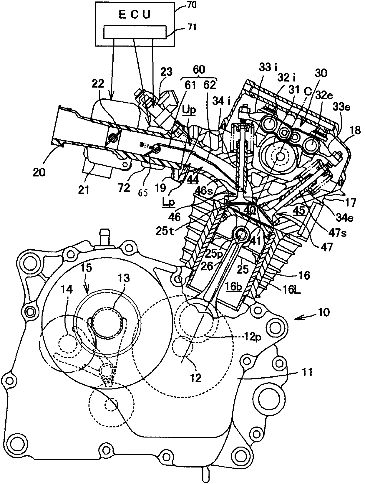
Technical field [0001] The present invention relates to an air intake device for an internal combustion engine mounted on a vehicle. Background technique [0002] There is a structure that constitutes an air intake device, that is, in the low load region of the internal combustion engine, in order to reduce the combustion efficiency, the intake air is tumbled in the combustion chamber and the fuel is delivered to the ignition plug in the upper part of the combustion chamber. Layered around, thereby improving combustion efficiency. [0003] The intake port and the exhaust port bend and extend in directions separating from each other from the intake valve port and the exhaust valve port on the upper top surface of the combustion chamber of the cylinder head. The intake air drawn from the inner edge side of the cylinder shaft (the central axis of the cylinder bore) close to the intake valve port into the center of the combustion chamber flows into the exhaust side while descending to...

Claims


Application Information

Patent Timeline
Patent Type & Authority Patents(China)
IPC IPC(8): F02B27/02
CPCY02T10/12
Inventor 饭岛智司白砂贵盛浅田雅也松井宏次
Owner HONDA MOTOR CO LTD
Learn More