
A magnetized levitation induction driven reaction momentum ball

A reaction and momentum ball technology, applied in the aerospace field, can solve problems such as poor immunity, complex control, and low drive efficiency, and achieve strong load-carrying and anti-interference capabilities, ensure system performance, and control easily.

Inactive Publication Date: 2017-11-07
CHINA ACADEMY OF SPACE TECHNOLOGY
View PDF1 Cites 0 Cited by
  • Summary
  • Abstract
  • Description
  • Claims
  • Application Information

AI Technical Summary

Problems solved by technology

[0004] The technical problem solved by the present invention is: to overcome the deficiencies of the prior art, to provide a magnetized levitation induction driven reaction momentum ball, which solves the problems of complex control, poor immunity and low driving efficiency

Method used


Image

  • A magnetized levitation induction driven reaction momentum ball
  • A magnetized levitation induction driven reaction momentum ball
  • A magnetized levitation induction driven reaction momentum ball

Examples


Embodiment Construction

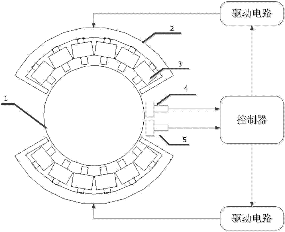
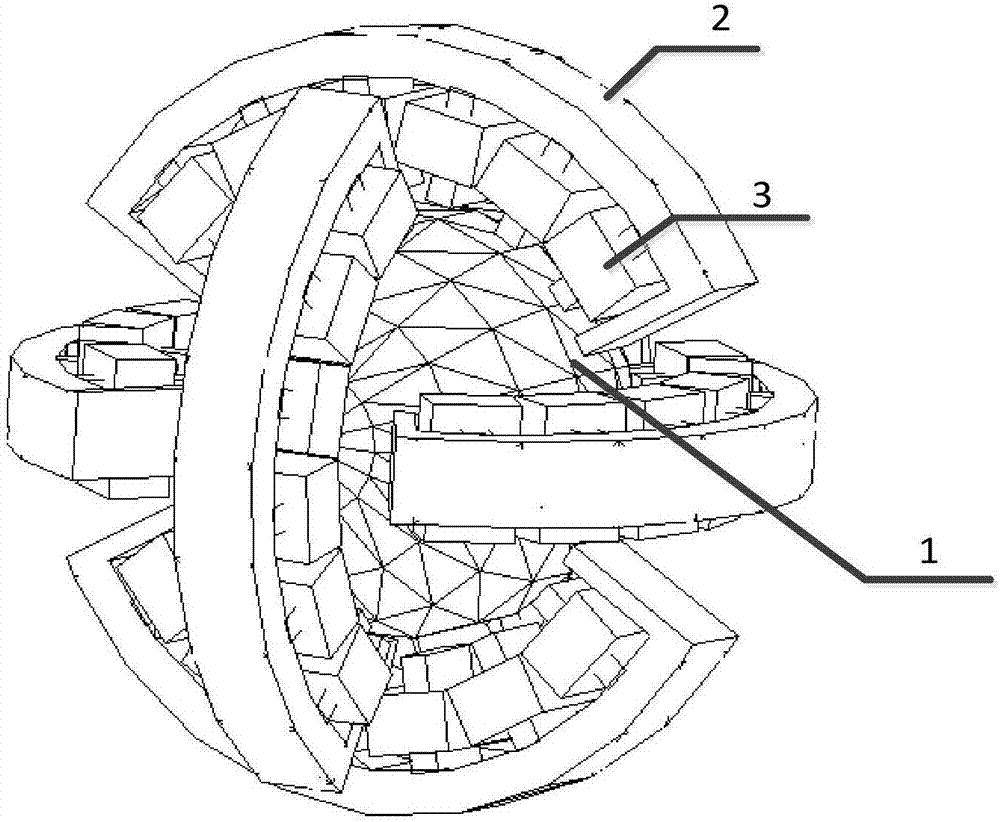
[0025] The components of the magnetized levitation induction-driven reaction momentum ball of the present invention include: a spherical rotor 1, an arc-shaped stator composed of an arc-shaped yoke 2 and a coil 3, a displacement sensor 4, a rotational speed sensor 5, a controller and a drive circuit.

[0026] Such as figure 1 Shown is the block diagram of the application of the invention composition system. In order to express clearly, only one axis is drawn in the figure as an illustration. The other two axes are exactly the same as this axis, but the controller can be shared by three axes. The position of the spherical rotor 1 in the electrode cage formed by the arc stator (composed of the arc yoke 2 and the coil 3) can be detected by the capacitive or photoelectric displacement sensor 4, and the controller uses The PID feedback algorithm controls the driving circuit to load current to the coil 3, so that a differential DC magnetic field is generated in the stator, which can...


PUM


Abstract

The invention provides a magnetization suspension induction drive type counteractive momentum ball which comprises a spherical rotor, arc-shaped stators, a displacement sensor, a rotation speed sensor, a controller and a drive circuit. The spherical rotor serves as a carrier for angular momentum exchange, is suspended in a coil cage composed of the six arc-shaped stators and controlled by electromagnetic force generated by the current in coils and rotates around any axis. The six arc-shaped stators and an aircraft body are fixed into a whole, and each arc-shaped stator comprises an arc-shaped magnet yoke with teeth and the coils wound around the arc-shaped magnet yoke. The displacement sensor detects the position of the spherical rotor in the coil cage composed of the arc-shaped stators and transmits a position signal to the controller. The rotation speed sensor detects the rotation speed of the spherical rotor relative to the arc-shaped stators and transmits a rotation speed signal to the controller. The controller generates a suspension drive control signal according to the position signal and generates a rotation drive control signal according to the rotation speed signal. The drive circuit amplifies a control signal generated by the controller and loads the control signal on the coils to generate the current.

Description

technical field [0001] The invention belongs to the aerospace field and relates to a reaction momentum ball used for satellite attitude adjustment. Background technique [0002] At present, the attitude of an orbiting spacecraft is mainly controlled by a reaction flywheel or a momentum wheel. However, flywheels or momentum wheels are single-axis angular momentum exchange devices. In order to achieve three-axis attitude control of the spacecraft, at least three sets of flywheels or momentum wheels are required, which brings limitations in system quality, power consumption, and efficiency. In addition, due to the friction between the shaft and the bearing, the control accuracy and life of the system are greatly limited. [0003] The publication number is WO2010117819A1, and the patent titled Reaction sphere for spacecraft attitude control (spacecraft attitude control reaction ball) discloses a reaction sphere. The electromagnetic pole cage of the reaction sphere is composed o...

Claims


Application Information

Patent Timeline
Patent Type & Authority Patents(China)
IPC IPC(8): B64G1/28
CPCB64G1/283B64G1/285
Inventor 范达范春石贺杨宋坚张南
Owner CHINA ACADEMY OF SPACE TECHNOLOGY
Learn More