
A high-pressure reheating gas-steam combined cycle power generation system and power generation method

A power generation system and high-pressure technology, which is applied in the field of high-pressure reheat gas-steam combined cycle power generation system, can solve the problems of high cost and high technical requirements of gas turbine equipment, and achieve the effect of reducing the difficulty of starting

Active Publication Date: 2016-03-23
GUODIAN NEW ENERGY TECH INST
View PDF5 Cites 0 Cited by
  • Summary
  • Abstract
  • Description
  • Claims
  • Application Information

AI Technical Summary

Problems solved by technology

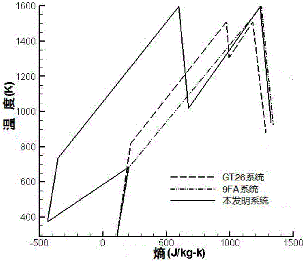
As for the GT26 system, it uses a sequential combustion device (Sequential Combustion Systems) and uses a reheat cycle to achieve a higher pressure ratio. A group of 22-stage high-efficiency subsonic compressors compress the air at a high pressure that is twice the pressure ratio of a conventional gas turbine. Pressed into the ring-shaped environment-friendly combustion chamber, which has extremely high technical requirements for gas turbine equipment and is expensive

Method used


Image

  • A high-pressure reheating gas-steam combined cycle power generation system and power generation method
  • A high-pressure reheating gas-steam combined cycle power generation system and power generation method
  • A high-pressure reheating gas-steam combined cycle power generation system and power generation method

Examples


Embodiment 1

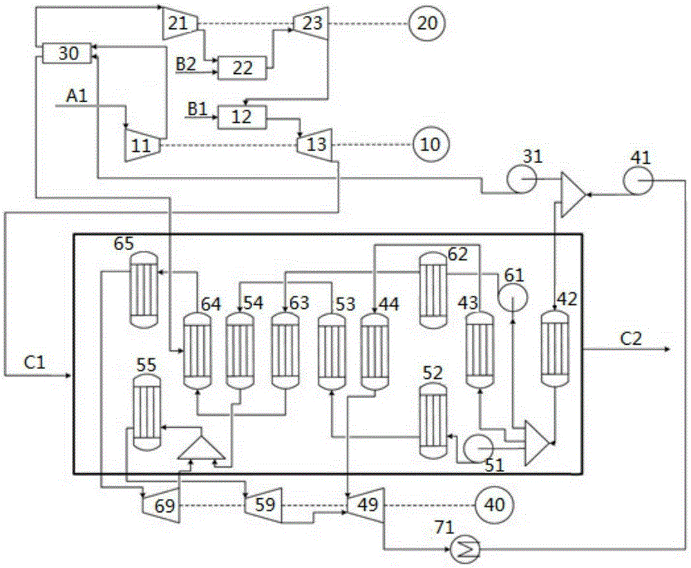
[0064] The power generation system structure of this embodiment is as follows figure 1 shown.

[0065] In the gas turbine subsystem, the medium pressure gas turbine 13 is coaxial with the primary compressor 11, the high pressure gas turbine 23 is coaxial with the secondary compressor 21, and the gas turbine is connected to the generators 10 and 20; the high pressure system and the medium The pressure system adopts split shaft arrangement;

[0066] In the steam turbine subsystem, a triple-pressure reheating waste heat boiler and a steam turbine are set. The specific structure is: the water supply structure is divided into high, medium and low pressure water lines, and the steam turbine is provided with a high pressure cylinder 69, a medium pressure cylinder 59 and a low pressure cylinder 49. Condenser 71 is connected to low-pressure water pump 41. After pressurization, it is divided into two routes. One route is connected to cold water pump 31, intercooler 30, high-pressure ...

Embodiment 2

[0070] The difference between this embodiment and embodiment 1 is that the high, medium and low cylinder intake air intake temperatures in the steam generation sub-system are respectively set to 540°C, 540°C and 305°C; the rest of the structure and parameters are the same as those in embodiment 1 Basically stay the same.

Embodiment 3

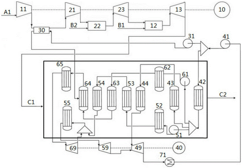
[0072] The power generation system structure of this embodiment is as follows figure 2 shown. The difference between this embodiment and Embodiment 1 is that the high-voltage system and the medium-voltage system adopt a coaxial arrangement; other structures and parameters are consistent with Embodiment 1.


PUM


Abstract

The invention relates to a high-pressure reheating gas-steam combined cycle power generation system and a power generation method. The system consists of a gas turbine sub-system and a steam turbine sub-system. The gas turbine sub-system comprises a device used for two-stage air compression, twice combustion as well as high-pressure and medium-pressure twice turbine working; after initial working of high-temperature gas, the high-temperature gas enters a medium-pressure combustion chamber and is reheated for secondary working, improving the average heat absorption temperature of the whole cycle; and at least a one-stage intercooler is arranged between two-stage compressors, and the heat flow of the intercooler is connected with the two-stage compressors. The steam turbine sub-system adopts a three-pressure reheating type boiler and a steam turbine, the cooling water of the intercooler is connected with high-pressure water, and high-pressure, medium-pressure and low-pressure water as well as the cooling water of the intercooler absorbs heat at different stages for multiple times, thus utilizing the heat energy efficiently. When the high-pressure reheating gas-steam combined cycle power generation system by the present invention is operated with the optimum parameters, the combined cycle efficiency is increased by 3-5 percentage points compared with a combined cycle system mainly adopting a gas turbine class F, and the single-machine output power is increased by more than 70%, reaching level 800MW.

Description

technical field [0001] The invention relates to a gas-steam combined cycle power generation device, in particular to a high-pressure reheated gas-steam combined cycle power generation system. The present invention also relates to a power generation method that can use the power generation system. Background technique [0002] The most commonly used steam cycle method for traditional thermal power generation is the Rankine cycle (Rankine Cycle), but the power generation technology based on the Rankine cycle has problems such as low power generation efficiency, large coal consumption, and serious pollution. The traditional steam cycle power generation method can no longer meet the needs of sustainable social and economic development. As fossil energy, the non-renewability of coal and petroleum resources and the increasingly severe environmental problems have made researchers pay more and more attention to energy-saving and clean power generation technologies. superior. Gas t...

Claims


Application Information

Patent Timeline
Patent Type & Authority Patents(China)
IPC IPC(8): F02C6/00F01K23/02
CPCF01K5/02Y02E20/16
Inventor 郭桦付忠广杨天亮卢可贾金祥
Owner GUODIAN NEW ENERGY TECH INST
Learn More