
Lens adjustment device and projector

A technology of adjusting device and lens, applied in the field of lens, can solve the problems of large space occupied by the lens adjusting device and unfavorable space configuration of other parts, etc.

Inactive Publication Date: 2016-09-07
QISDA OPTRONICS (SUZHOU) CO LTD +1
View PDF6 Cites 1 Cited by
  • Summary
  • Abstract
  • Description
  • Claims
  • Application Information

AI Technical Summary

Problems solved by technology

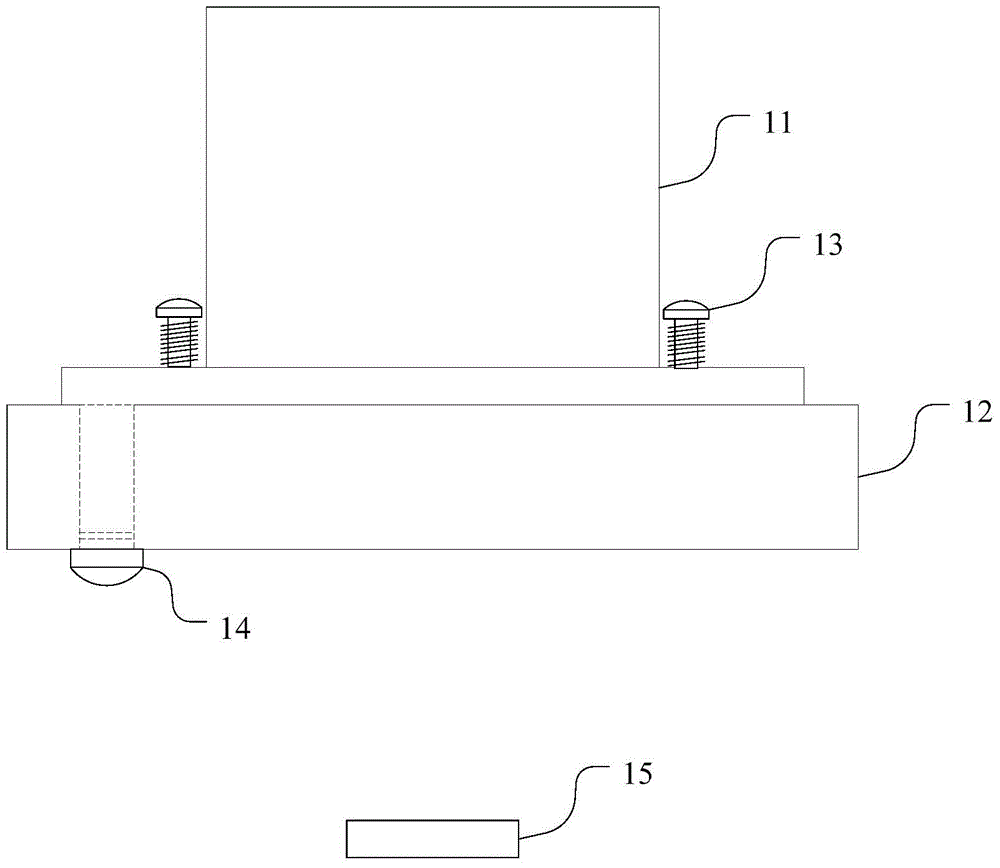
[0004] figure 1 Although the lens adjustment device shown can adjust the direction of the lens, the moving direction of the adjustment screw is the same as the direction in which the lens holder 11 is pushed, which makes the entire lens adjustment device occupy a large space, which is not conducive to the space of other parts. configuration

Method used


Image

  • Lens adjustment device and projector
  • Lens adjustment device and projector
  • Lens adjustment device and projector

Examples


Embodiment Construction

[0025] In order to have a further understanding of the purpose, structure, features, and functions of the present invention, the following detailed descriptions are provided in conjunction with the embodiments.

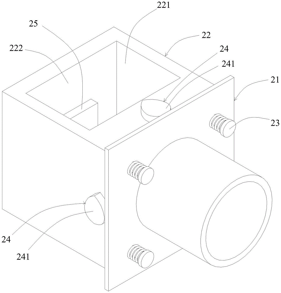
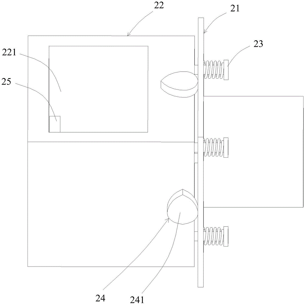
[0026] figure 2 A schematic view showing an angle of view of an embodiment of the lens adjustment device provided by the present invention, image 3 show figure 2 Schematic diagram of another viewing angle of the medium-lens adjustment device, Figure 4 show figure 2 A schematic diagram of another viewing angle of the medium lens adjustment device, wherein Figure 4 Lines that are not actually visible are shown as dotted lines. See also Figure 2 to Figure 4 , The lens adjustment device in this embodiment includes a lens holder 21, a holder 22, an elastic connector 23 and two adjustment screws 24 with cam-shaped nuts.

[0027] The lens fixing seat 21 is used for installing and fixing the lens therein. In this embodiment, the lens fixing seat 21 includes a len...


PUM


Abstract

An embodiment of the present invention provides a lens adjustment device and a projector, the lens adjustment device includes: a lens fixing base, a fixing frame, an elastic connector and at least two adjustment screws with cam-shaped nuts; wherein the elastic connector The lens fixing seat and the fixing frame are pulled closer to each other by elastic force, the adjusting screw is screwed on the fixing frame, and the cam profile surface of the nut of the adjusting screw and the lens fixing seat face toward the fixing One side of the frame is against each other, and the lens holder is pushed to deflect by turning the cam-shaped nut of the adjustment screw. The embodiments of the present invention can reduce the space occupied by the lens adjusting device.

Description

technical field [0001] The invention relates to the lens field, in particular to a lens adjustment device and a projector. Background technique [0002] It is often necessary to adjust the direction of the lens in the optical field where the lens is used. For example, in a projector using a DMD, the direction of the lens needs to be adjusted so that the lens is parallel to the DMD. [0003] figure 1 A schematic diagram of a lens adjustment device in the prior art is shown, the lens adjustment device includes a lens fixing seat 11, a fixing plate 12 and an adjustment screw 14, the lens fixing seat 11 is pressed to the fixing plate 12 by a spring screw 13, and the adjustment The screw 14 is penetrated in the fixing plate 12 to adjust the direction of the lens fixing seat 11, and then realize adjusting the direction of the lens fixedly installed in the lens fixing seat 11, so that the lens is parallel to the DMD15. [0004] figure 1 Although the lens adjustment device shown ...

Claims


Application Information

Patent Timeline
Patent Type & Authority Patents(China)
IPC IPC(8): H04N5/74G02B7/02
Inventor 萧启宏
Owner QISDA OPTRONICS (SUZHOU) CO LTD
Learn More