Microwave heating device
A microwave heating device and microwave technology are applied in microwave heating, electric heating device, electric/magnetic/electromagnetic heating and other directions to achieve the effects of suppressing reflected wave components, high reliability, and preventing temperature rise
- Summary
- Abstract
- Description
- Claims
- Application Information
AI Technical Summary
Problems solved by technology
Method used
Image

Examples
Embodiment approach 1
[0061] As Embodiment 1 of this invention, the heating cooker in a microwave heating apparatus is demonstrated. In addition, in each of the following embodiments, a microwave oven having at least one heater will be described as an example of the heating means of the heating cooker.
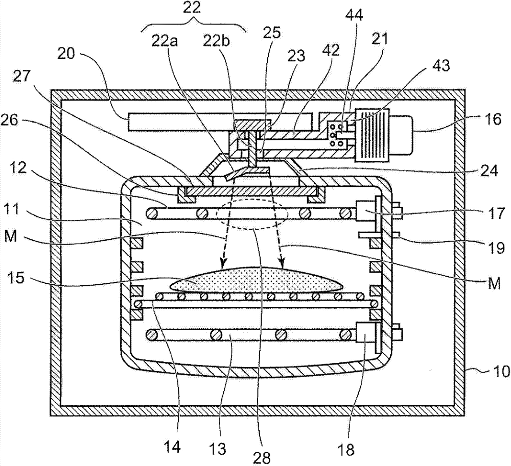
[0062] figure 1 It is a front sectional view showing the internal structure of main parts in the heating cooker which is the microwave heating device according to Embodiment 1 of the present invention. exist figure 1 In the shown heating cooker, a heating chamber 11 for medium heating (high-frequency heating) of food 15 as an object to be heated is provided inside a casing 10 constituting the outer appearance of the heating cooker. That is, in the heating chamber 11, the food 15 as an object to be heated is accommodated, microwaves are radiated to the food 15, and high-frequency heating is performed. Inside the heating chamber 11 formed of a steel plate with an enamel-coated surface, two upper...
Embodiment approach 2
[0111] Hereinafter, a heating cooker according to Embodiment 2 will be described as an example of the microwave heating device of the present invention. The heating cooker according to Embodiment 2 is largely different from the above-described heating cooker according to Embodiment 1 in the structure for supplying microwaves to the heating chamber.
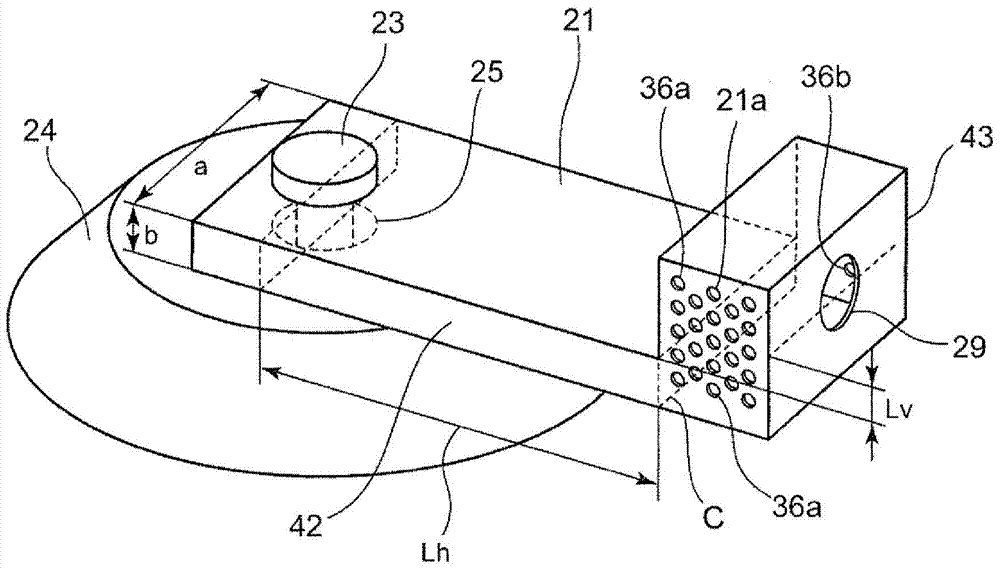
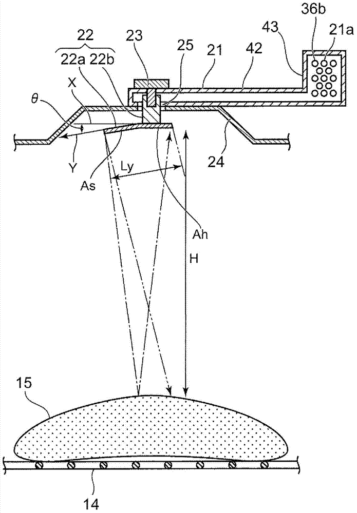
[0112] In the following description of the heating cooker according to Embodiment 2, elements having the same functions and structures as those of the heating cooker according to Embodiment 1 are assigned the same reference numerals, and the detailed description thereof applies to Embodiment 1. instruction of. Figure 4 It is a front sectional view showing the internal structure of a main part in the heating cooker of Embodiment 2. Figure 5 yes Figure 4 Side cutaway view of the heating cooker shown.
[0113] Such as Figure 4 and Figure 5 As shown, in the heating cooker according to the second embodiment, the waveguide 21 ...
Embodiment approach 3
[0138] Hereinafter, a heating cooker according to Embodiment 3 will be described as an example of the microwave heating device of the present invention. The heating cooker of Embodiment 3 is largely different from the heating cookers of Embodiments 1 and 2 described above in the structure for supplying microwaves to the heating chamber. In the heating cooker of Embodiment 3, the configuration of Embodiment 1 or Embodiment 2 is applied to other configurations.
[0139] In the following description of the heating cooker of Embodiment 3, elements having the same functions and structures as those of the heating cookers of Embodiments 1 and 2 are attached with the same reference numerals, and the detailed description thereof is as follows: The description of Embodiment Mode 1 and Embodiment Mode 2 applies.
[0140] Figure 8 and Figure 9 It is a sectional view of main parts showing a power supply unit and an object to be heated in the heating cooker according to Embodiment 3. ...
PUM
 Abstract
Description
Claims
Application Information