
A cutting tool with adjustable leading angle

A cutting tool and leading angle technology, which is applied to lathe tools, turning equipment, hand-held tools, etc., can solve the problem that the leading angle cannot be continuously adjusted, the leading angle cannot be continuously adjusted, and the cost of cutting processing Increase and other issues, to achieve the effect of reducing auxiliary processing time, increasing the rate of repeated utilization, and facilitating processing and production

Active Publication Date: 2016-09-07
ZHUZHOU CEMENTED CARBIDE CUTTING TOOLS CO LTD
View PDF5 Cites 0 Cited by
  • Summary
  • Abstract
  • Description
  • Claims
  • Application Information

AI Technical Summary

Problems solved by technology

[0002] In the engine hole processing industry, it is often encountered that the hole needs to be chamfered. The metal cutting tools used for this type of processing usually use different cutting tool angles to process different chamfer angles. The traditional method is to use The solution is to change the tool, which will lead to an increase in the frequency of tool changes in the cutting process, which reduces the processing efficiency and increases the processing cost
Chinese patent CN 98804441 discloses a tool holder for selectively processing the cutting workpiece with an adjustable lead angle (that is, the entering angle) at 30°, 45° or 60°. The tool holder structure recorded in this document solves the problem of In the above three cases, the chamfering process can be completed on the same tool holder without changing the tool, but the continuous adjustment of the leading angle is not realized, and the continuous value of the leading angle between the above three leading angles cannot be realized. continuous adjustment
In addition, when chamfering some holes, the customer has strict requirements on the tolerance of the chamfering angle. At this time, high-precision tools are required, which increases the cost of cutting processing.

Method used


Image

  • A cutting tool with adjustable leading angle
  • A cutting tool with adjustable leading angle
  • A cutting tool with adjustable leading angle

Examples


Embodiment Construction

[0023] The present invention will be described in further detail below in conjunction with specific embodiment and accompanying drawing, it should be pointed out that protection scope of the present invention is not only limited to following embodiment, for those of ordinary skill in the art, without departing from the principle premise of the present invention The following improvements and modifications should also be considered as protection scope of the present invention.

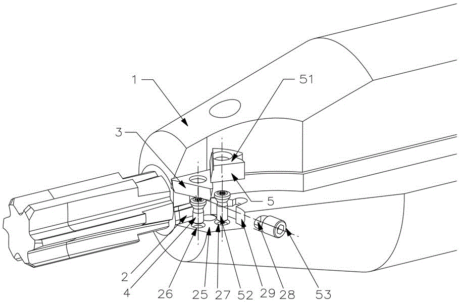
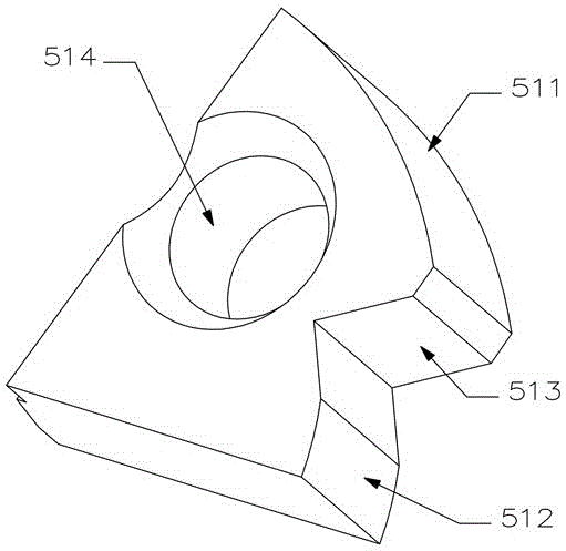
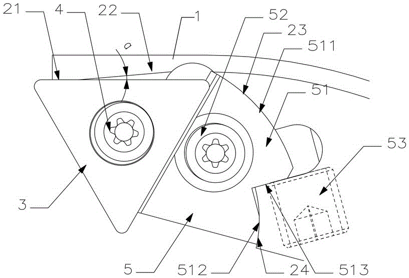
[0024] Figure 1 to Figure 4 An embodiment of the present invention is shown. The cutting tool with adjustable entering angle of this embodiment includes a tool body 1, a cutting blade 3 and an adjustment block 51. The tool body 1 is provided with a sipe 2, and the sipe 2 includes A sipe bottom 25 and a sipe side 29 . The bottom surface of the knife groove 25 is provided with a blade screw hole 26 and an adjustment block screw hole 27. The cutting blade 3 is pressed on the bottom surface of the knife g...


PUM


Abstract

The invention discloses a cutting tool with the adjustable tool cutting edge angle. The cutting tool comprises a tool body, a cutting blade and an adjusting block. A tool groove is formed in the tool body and comprises a tool groove bottom face and a tool groove side face, the cutting blade is compressed on the tool groove bottom face through a blade compression screw, the adjusting block is compressed on the tool groove bottom face through an adjusting block compression screw, the cutting blade and the adjusting block are in contact fit, a first tool groove positioning face is arranged on the tool groove side face, a first adjusting block positioning face which is in contact fit with the first tool groove positioning face is arranged on the adjusting block, both the first tool groove positioning face and the first adjusting block positioning face are arc-shaped faces, and a drive part for driving the adjusting block to rotate around the adjusting block compression screw is installed on the tool body. The cutting tool is simple in structure, convenient to machine and manufacture, and high in adjusting accuracy, continuous adjustment of the tool cutting edge angle can be achieved, machining efficiency can be improved, and production cost can be lowered.

Description

technical field [0001] The invention mainly relates to the technical field of metal cutting, in particular to a cutting tool with adjustable leading angle. Background technique [0002] In the engine hole processing industry, it is often encountered that the hole needs to be chamfered. The metal cutting tools used for this type of processing usually use different cutting tool angles to process different chamfer angles. The traditional method is to use The solution is to change the tool, which will lead to an increase in the frequency of tool changes in the cutting process, which reduces the processing efficiency and increases the processing cost. Chinese patent CN 98804441 discloses a tool holder for selectively processing the cutting workpiece with an adjustable lead angle (that is, the entering angle) at 30°, 45° or 60°. The tool holder structure recorded in this document solves the problem of In the above three cases, the chamfering process can be completed on the same t...

Claims


Application Information

Patent Timeline
Patent Type & Authority Patents(China)
IPC IPC(8): B25B27/00
CPCB23B27/00B23B27/1685
Inventor 贺鑫刘敏王社权向侠
Owner ZHUZHOU CEMENTED CARBIDE CUTTING TOOLS CO LTD
Learn More