Demolding device and demolding method
A demoulding device and demoulding technology, applied in the field of injection molding, can solve problems such as deformation of injection molded workpieces and easily damaged surfaces, and achieve the effects of rapid demoulding, high technical quality requirements, and improved labor productivity
- Summary
- Abstract
- Description
- Claims
- Application Information
AI Technical Summary
Problems solved by technology
Method used
Image

Examples
Embodiment 1
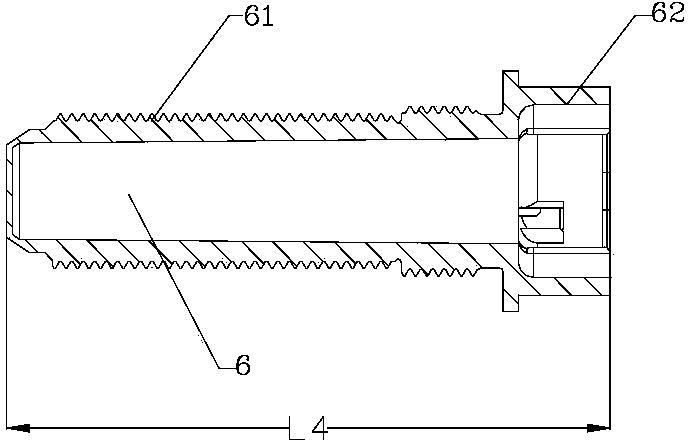
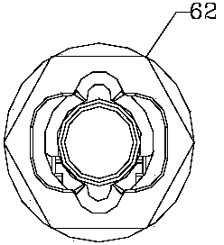
[0059] Such as figure 1 and figure 2 As shown, the injection molded workpiece 6 in this embodiment is a fully threaded screw, and after injection molding, the length L4 of the injection molded workpiece 6 is 80 mm.
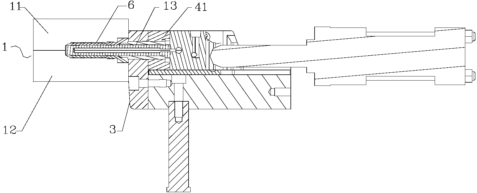
[0060] Such as Figure 6 As shown, the demoulding device of this embodiment is used for the demoulding of the injection molding workpiece 6 in the mold 1, comprising: a base 2, which is arranged on one side of the mold 1, and can move up and down relative to the mold 1; a stopper 3, which is set Between the mold 1 and the base 2 and fixedly connected with the base 2 by the first screw 81, the stopper 3 is provided with a through hole 31, the size of the through hole 31 is smaller than the size of the contact end of the injection molded workpiece 6 and the stopper 3; the drive assembly 4, Fixedly connected with one end of the insert pin 13 of the mold 1 outside the cavity of the mold 1, the insert pin 13 can pass through the through hole 31 on the block 3 and ex...
PUM
 Abstract
Description
Claims
Application Information