
Suspension system for electric vehicle power assembly

A powertrain and suspension system technology, applied in power plants, vehicle parts, jet propulsion devices, etc., can solve problems such as high cost, large rubber mount volume, and poor vibration isolation effect, and achieve vibration isolation capability high effect

Active Publication Date: 2014-04-16
ANHUI JIANGHUAI AUTOMOBILE GRP CORP LTD
View PDF6 Cites 23 Cited by
  • Summary
  • Abstract
  • Description
  • Claims
  • Application Information

AI Technical Summary

Problems solved by technology

In the development process of electric vehicles, it is cost-effective to use the same frame as that of traditional fuel engine vehicles. The gap between them will be very large, in other words, the distance between the powertrain and the frame rail is very "far". In this case, if the traditional three or four rubber mounts are still used to connect the powertrain, Then the rubber mount has a large volume, the span of the connection points at both ends of the mount is large, the cost is high, and the rigidity of the mount is not enough, and it cannot meet the requirements of NVH and safety.
[0003] The main consideration of the existing electric vehicle powertrain mount is how to save the space in the powertrain cabin, so a hoisting suspension system is adopted, that is, the hoisting beam is connected to the mount, and then the powertrain is hoisted on the On the hoisting beam, this suspension system has a certain vibration isolation capability, but the vibration isolation effect is not very good
In addition, this hoisting and suspension system does not take into account how to meet the anti-collision requirements of electric vehicles after the powertrain is reduced.

Method used


Image

  • Suspension system for electric vehicle power assembly
  • Suspension system for electric vehicle power assembly

Examples


Embodiment Construction

[0019] In the following description in conjunction with the accompanying drawings, the left-right direction refers to the vehicle width direction, or lateral direction; the front-rear direction refers to the vehicle length direction, or longitudinal direction.

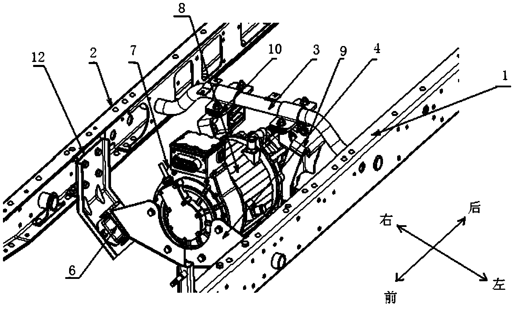
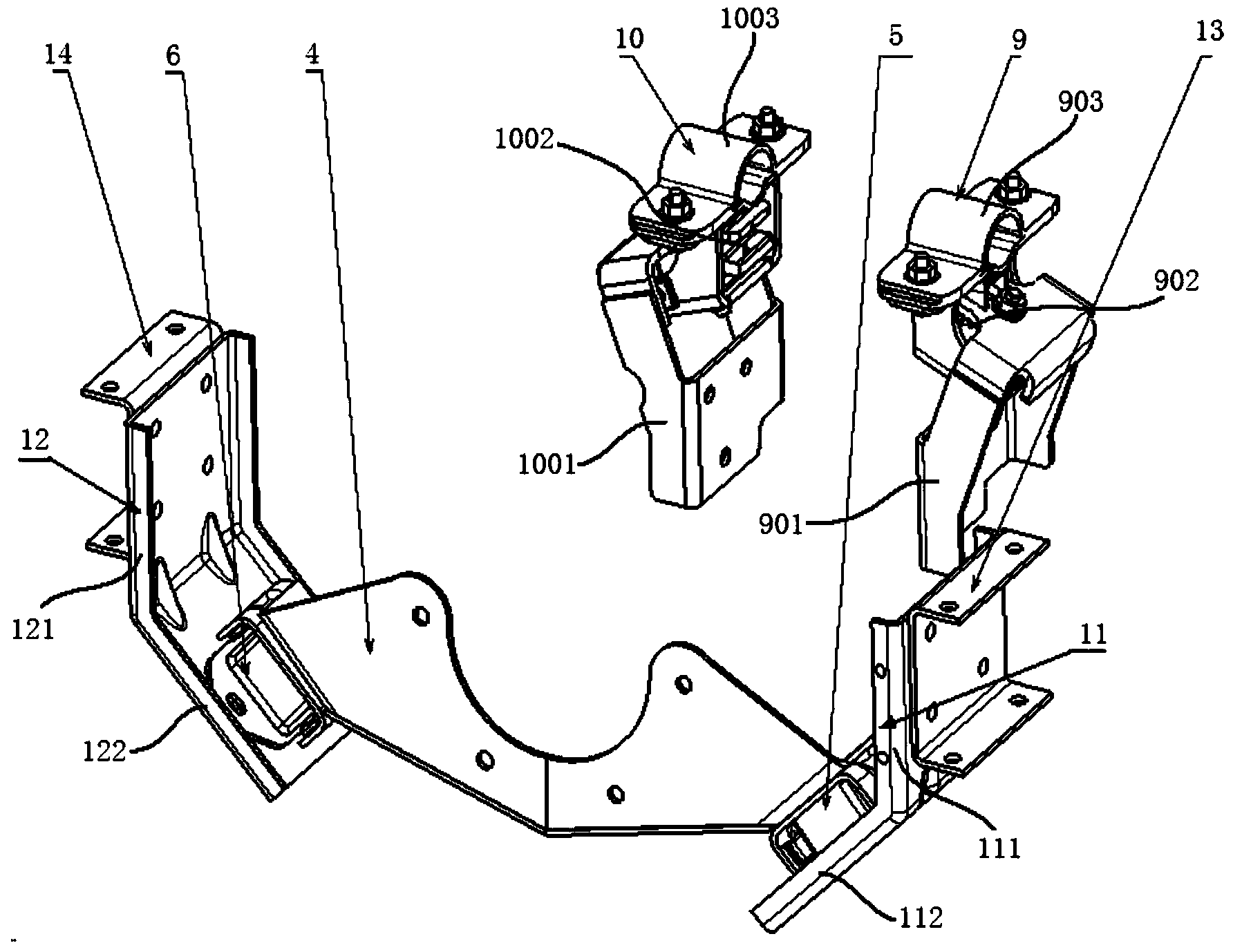
[0020] refer to figure 1 , in the development of electric vehicles, it is a more economical and quicker choice to use the frame of a traditional fuel engine vehicle. Overall it's too big. Of course, the embodiment of the present invention is not limited to the electric vehicle powertrain consisting of the electric motor 7 and the speed reducer 8 only. In this embodiment, both ends of the beam 3 are rigidly connected to the left longitudinal beam 1 and the right longitudinal beam 3 respectively, the plate-shaped bracket 4 and the beam 3 are arranged at intervals in the longitudinal direction, and the two ends of the plate-shaped bracket 4 are suspended by the left Set the cushion 5 ( figure 2 shown in) and the right...


PUM


Abstract

The invention provides a suspension system for an electric vehicle power assembly. The suspension system comprises a left longitudinal beam, a right longitudinal beam, a beam, plate brackets and a power assembly, wherein the beam is rigidly connected with the left longitudinal beam and the right longitudinal beam; the plate brackets are arranged on the beam in the longitudinal direction at intervals; two ends of each plate bracket are connected with the left longitudinal beam and the right longitudinal beam by virtue of a left suspension cushion and a right suspension cushion; the front part of the power assembly is rigidly connected with the plate brackets in the vertical direction; the rear part of the power assembly is hoisted on the beam by virtue of a left suspension assembly and a right suspension assembly. By adopting the suspension system disclosed by the invention, the space arrangement requirements, anti-vibration performance requirements and anti-collision requirements of the electric vehicle power assembly can be simultaneously met when the electric vehicle is manufactured by adopting the frame of the traditional fuel power train vehicle.

Description

technical field [0001] The invention relates to the field of electric vehicles, in particular to an electric vehicle powertrain suspension system. Background technique [0002] In the current automobile industry environment, pure electric vehicles have gained the attention of domestic and foreign automobile manufacturers, and they are making great efforts to carry out industrialization research and development. The powertrain of an electric vehicle is a fuel engine and a gearbox that replace the transmission with an electric motor and a reducer, and the volume becomes smaller. In the development process of electric vehicles, it is cost-effective to use the same frame as traditional fuel engine vehicles, but at this time, due to the unchanged frame space, the electric vehicle powertrain (motor and reducer) and frame rails, etc. The gap between them will be large, in other words, the distance between the powertrain and the frame rail is very "far". In this case, if the tradit...

Claims


Application Information

Patent Timeline
Patent Type & Authority Applications(China)
IPC IPC(8): B60K5/12
Inventor 孔晓春夏顺礼李文杰
Owner ANHUI JIANGHUAI AUTOMOBILE GRP CORP LTD
Learn More