AI technical title is built by Patsnap AI team. It summarizes the technical point description of the patent document.
A technology for camera devices and vehicles, which is applied to vehicle parts, optical observation devices, image communication, etc., can solve the problems of aesthetics degradation and achieve the effect of improving aesthetics and inhibiting damage
Inactive Publication Date: 2014-04-16
HONDA ACCESS CORP
View PDF6 Cites 8 Cited by
Summary
Abstract
Description
Claims
Application Information
AI Technical Summary
This helps you quickly interpret patents by identifying the three key elements:
Problems solved by technology
Method used
Benefits of technology
Problems solved by technology
[0004] However, the mounting structure of the vehicle imaging device described in the above-mentioned Patent Document 1 has a problem that the aesthetics of the vehicle imaging device are exposed to the outside.
Therefore, it is considered to improve the aesthetics by covering the imaging device with a decorative member. However, with the above-mentioned conventional mounting structure of the imaging device for a vehicle, if the position and angle of the imaging device are adjusted, the position of the tip of the imaging device will move greatly. , so in order to avoid interference with the camera device, the decorative components are inevitably enlarged, which may lead to a decrease in aesthetics
Method used
Image
Click on the blue label to locate the original text in one second.
Reading with bidirectional positioning of images and text.
Examples
no. 1 Embodiment approach
[0022] Below, according to Figure 1 to Figure 4 The first embodiment of the present invention will be described.
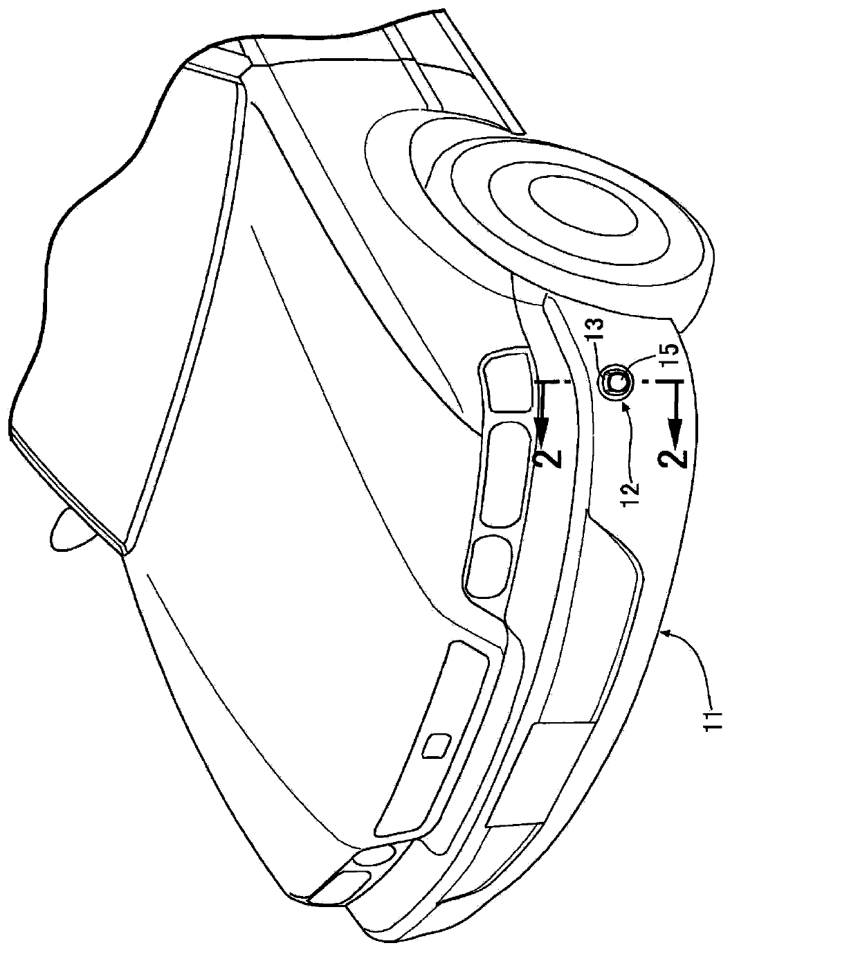
[0023] Such as figure 1 As shown, a camera unit 12 is installed at the corner of the front bumper 11 of the motor vehicle, and by displaying an image near the corner of the front bumper 11 captured by the camera unit 12 on a monitor in the vehicle compartment, the driver can be assisted. This is to prevent the front bumper 11 from coming into contact with obstacles when the vehicle is parked or the like.
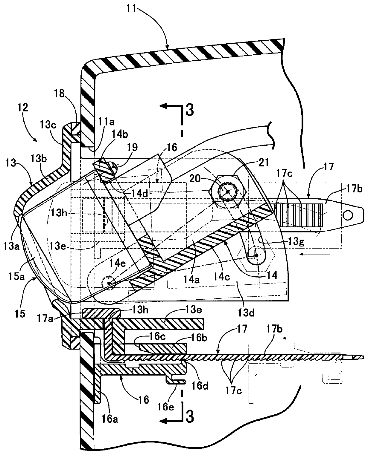
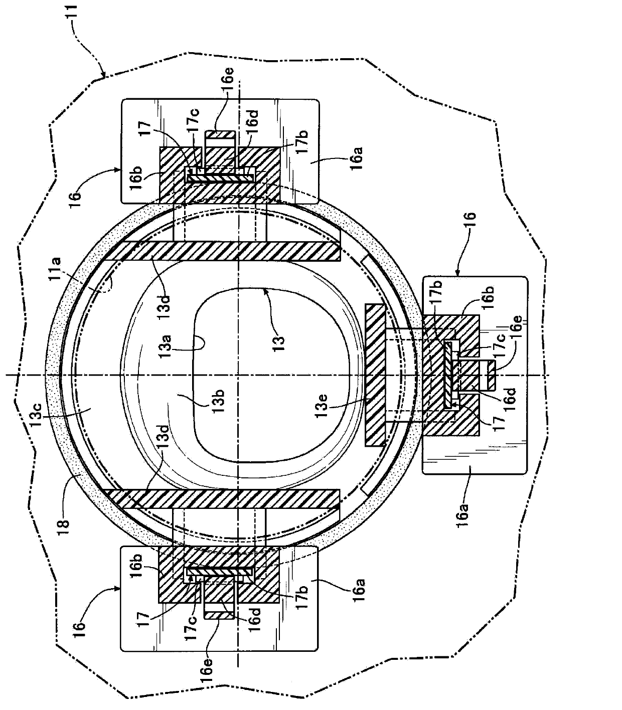
[0024] Such as Figure 2 ~ Figure 4 As shown, the camera unit 12 includes a decoration member 13, a mounting bracket 14, a camera device 15, three belt bases 16..., three belts 17... and a sealing member 18 formed by an O-ring.
[0025] fixed to the circular opening 11a formed in the front bumper 11 (see figure 2 ) at the decorative member 13 includes: a cover portion 13b protruding from the surface of the front bumper 11 and having a lens opening 13a at t...
no. 2 Embodiment approach
[0039] Below, according to Figure 5 with Image 6 A second embodiment of the present invention will be described.
[0040] In the second embodiment, the fixing structure of the decorative member 13 to the opening 11 a of the front bumper 11 is different from that of the first embodiment, and the other structures are the same as those of the first embodiment.
[0041] The decorative member 13 of the second embodiment has an external thread portion 13i on the outer peripheries of the pair of side walls 13d, 13d, and the annular first nut member 22 and second nut member 23 can be screwed to the external thread portion 13i. The seal member 18 has a U-shaped cross-section and is attached to the opening 11a of the front bumper 11. The flange 13c comes into contact with the front surface of the seal member 18 when the decorative member 13 is inserted into the opening 11a.
[0042] By screwing the first nut member 22 and the second nut member 23 to the outer threaded portion 13i of...
PUM
Abstract
The invention provides a mounting structure of a vehicle camera, which is easy in mounting angle adjustment and excellent in aesthetic appearance. A pin (14e) provided at a tip end side of a mounting bracket (14) is pivotally supported at a garnish (13) fixed to a vehicle body and a base end side of the mounting bracket (14) is fixed to the garnish (13) with at least two different angles by a bolt (20). Therefore, not only the mounting angle of a camera (15) can be easily adjusted, but also optimal images can be obtained by only adjusting the mounting angles of the common cameras (15) even if the mounting heights of the cameras (15) differ in accordance with vehicle types. Further, the pin (14e) is provided at the tip end side of the mounting bracket (14). Therefore, the protruding amount of the camera (15) supported at the mounting bracket (14) from the vehicle body is made small, the moving amount of a tip end of the camera (15) can be suppressed to a minimum at the time of adjustment of the angle to enhance aesthetic appearance, and in addition, the camera (15) can be protected by the mounting bracket (14).
Description
technical field [0001] The present invention relates to an attachment structure of an imaging device for a vehicle in which a mounting bracket for supporting the imaging device is attached to a decorative member fixed to a vehicle body. Background technique [0002] According to the following patent document 1, there is known a mounting structure of an imaging device for a vehicle in which spacers for position and angle adjustment are respectively mounted to a pair of long holes formed in the mounting bracket described below, The spacer and the bolts of the vehicle-mounted camera device are screwed with nuts, so that the vehicle-mounted camera device can be fixed to the mounting bracket at any position and angle, and the mounting bracket is fixed to the hatchback door of the motor vehicle. [0003] Patent Document 1: Japanese Unexamined Patent Publication No. 2011-213193 [0004] However, the mounting structure of the vehicle imaging device described in the above-mentioned ...
Claims
Application Information
Patent Timeline
Application Date:The date an application was filed.
Publication Date:The date a patent or application was officially published.
First Publication Date:The earliest publication date of a patent with the same application number.
Issue Date:Publication date of the patent grant document.
PCT Entry Date:The Entry date of PCT National Phase.
Estimated Expiry Date:The statutory expiry date of a patent right according to the Patent Law, and it is the longest term of protection that the patent right can achieve without the termination of the patent right due to other reasons(Term extension factor has been taken into account ).
Invalid Date:Actual expiry date is based on effective date or publication date of legal transaction data of invalid patent.

