Al technical title is built by PatSnap Al team. It summarizes the technical point description of the patent document.
A solar photovoltaic and module technology, applied in the field of solar energy, can solve the problems of waste of manpower and material resources, inability to adjust the angle, input and output limitations, etc., to achieve the effect of reducing the use of manpower, flexible use, and improving stability
Inactive Publication Date: 2018-03-16
温州爱作贸易有限公司
View PDF4 Cites 3 Cited by
Summary
Abstract
Description
Claims
Application Information
AI Technical Summary
This helps you quickly interpret patents by identifying the three key elements:
Problems solved by technology
Method used
Benefits of technology
Problems solved by technology
In the near future, solar photovoltaic power generation will not only replace some conventional energy sources, but also become the main body of the world's energy supply, which will bring revolutionary changes to energy development. Solar photovoltaic module brackets are important components for fixing solar panels. Under the premise of the maximum power generation efficiency of solar panels, ensuring the safety and reliability of the brackets is something that photovoltaic module manufacturers need to consider and study. At present, most of the commercialized solar photovoltaic module mounting brackets cannot adjust the angle, and the tracking method for solar power generation wastes a lot of manpower. Material resources and input-output ratio are limited to a certain extent
Method used
Image
Click on the blue label to locate the original text in one second.
Reading with bidirectional positioning of images and text.
Examples
Embodiment Construction
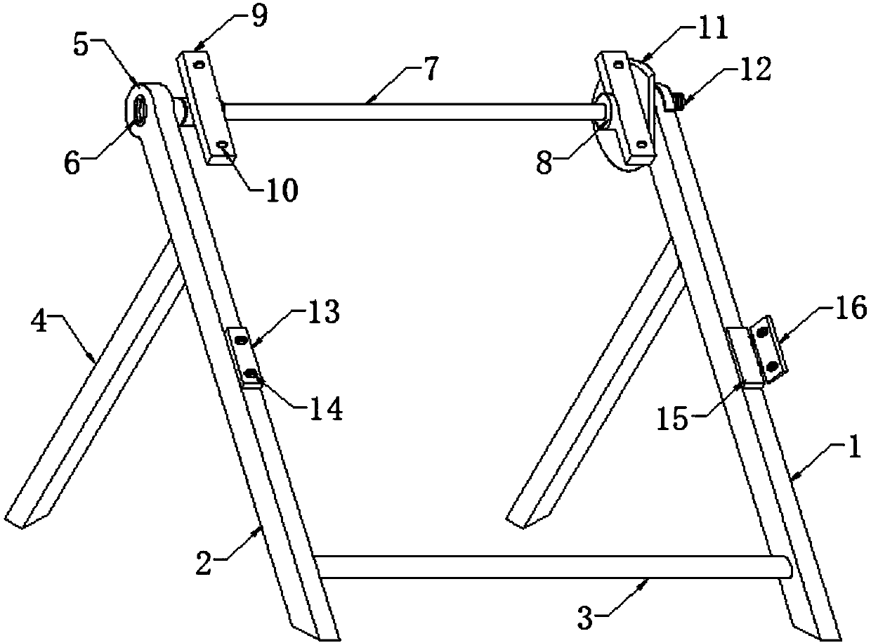
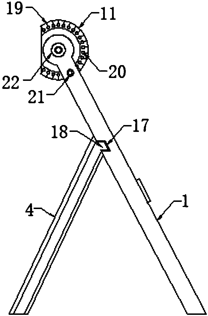
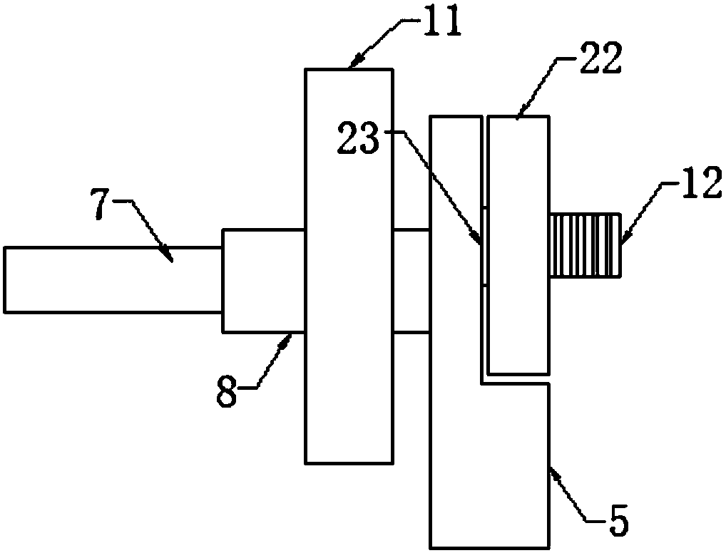
[0022] Such as Figure 1-4 As shown, this specific embodiment adopts the following technical solutions: a solar photovoltaic module support, including a first main support 1, a second main support 2, a cross bar 3, a support frame 4, a connecting head 5, a connecting hole 6, and a connecting rod 7. Bearing sleeve 8, support piece 9, mounting hole 10, scale positioning plate 11, connecting bolt 12, positioning plate 13, threaded hole 14, fixing plate 15, connecting plate 16, slot 17, pin 18, scale line 19, Positioning holes 20, plunger-type scale pins 21, movable discs 22, movable shafts 23, battery boards 24 and fastening pressure pieces 25, the first main bracket 1 and the second main bracket 2 are fixedly connected by a cross bar 3, the second The ends of a main bracket 1 and the second main bracket 2 are provided with connectors 5, and the connectors 5 are fixedly connected by connecting rods 7, and the two ends of the connecting rods 7 are movably nested with bearing sleev...
PUM
Abstract
The invention discloses a solar photovoltaic component bracket which includes a first main bracket, a second main bracket, a cross bar, support frames, connecting heads, connecting holes, a connectingrod, bearing sleeves, support pieces, mounting holes, a scale positioning disk, a connecting bolt, a positioning plate, threaded holes, a fixing plate, a connecting plate, slots, pins, scale lines, positioning holes, a plunger scale pin, a movable disk, a movable shaft, cell panels and fastening pressure pieces. The level angle can be adjusted as needed. The solar photovoltaic component bracket is not only suitable for ground photovoltaic power stations, but also suitable for roof photovoltaic power stations. The installation angle of the bracket can be quickly adjusted in the process of installation. The defect that the installation angle of the conventional photovoltaic component bracket cannot be quickly adjusted is avoided. Various requirements of photovoltaic component installation are satisfied. The device is flexible in use, and has high efficiency and high practicality. The device adapts to a variety of different working modes. The use of manpower is reduced.
Description
Technical field: [0001] The invention relates to the technical field of solar energy, in particular to a solar photovoltaic module bracket. Background technique: [0002] At present, under the circumstances of global energy supply shortage and increasingly serious environmental problems, the sustainable development of economy and society has been greatly challenged, and the development and utilization of clean and safe renewable energy have received extensive attention. Although there are many types of renewable alternative energy that have been utilized at present, from the perspective of the available total amount, water energy, wind energy, and tidal energy are too small to meet human needs. Solar energy, as a renewable energy with abundant resources, widespread distribution and permanent utilization, has great potential for development and utilization. Especially in the 21st century, the solar photovoltaic power generation industry has developed very rapidly. Solar pho...
Claims
Application Information
Patent Timeline
Application Date:The date an application was filed.
Publication Date:The date a patent or application was officially published.
First Publication Date:The earliest publication date of a patent with the same application number.
Issue Date:Publication date of the patent grant document.
PCT Entry Date:The Entry date of PCT National Phase.
Estimated Expiry Date:The statutory expiry date of a patent right according to the Patent Law, and it is the longest term of protection that the patent right can achieve without the termination of the patent right due to other reasons(Term extension factor has been taken into account ).
Invalid Date:Actual expiry date is based on effective date or publication date of legal transaction data of invalid patent.