Eureka AIR delivers breakthrough ideas for toughest innovation challenges, trusted by R&D personnel around the world.

Movable parking frame for parking cars in flat parking lot and using method

A technology for parking racks and parking lots, which is applied in the direction of buildings, building types, buildings, etc. where cars are parked. It can solve the problems that the parking position has a great influence and hinders the traffic in the field, and achieve the best parking effect.

Inactive Publication Date: 2014-04-16
高善一
View PDF6 Cites 2 Cited by
  • Summary
  • Abstract
  • Description
  • Claims
  • Application Information

AI Technical Summary

Problems solved by technology

At present, the parking of cars in the flat parking lot can only be realized by the movement of the car itself. The driver's operating level has a great influence on the occupancy of the parking space, and once the wrong location is parked, it will hinder the traffic in the field until the owner is waiting or driving. Only when someone arrives can it be resolved

Method used


Image

  • Movable parking frame for parking cars in flat parking lot and using method
  • Movable parking frame for parking cars in flat parking lot and using method

Examples


Embodiment 1

[0024] The driving control part adopts the foldable gantry crane device of the current existing technology; the lifting operation of the hoist adopts the current chain lifting principle and structure.

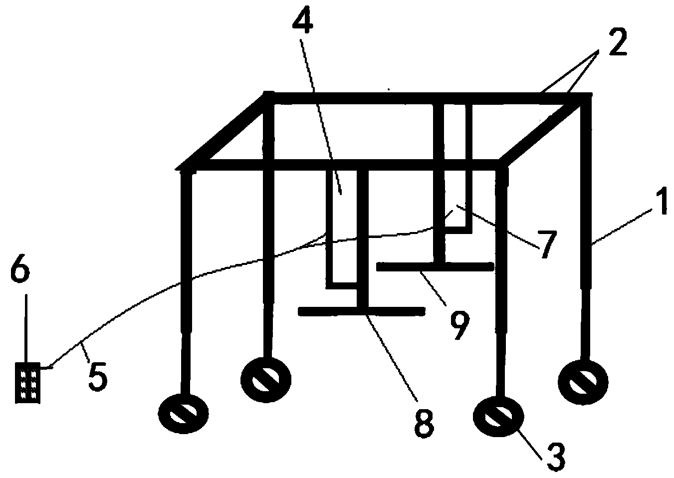
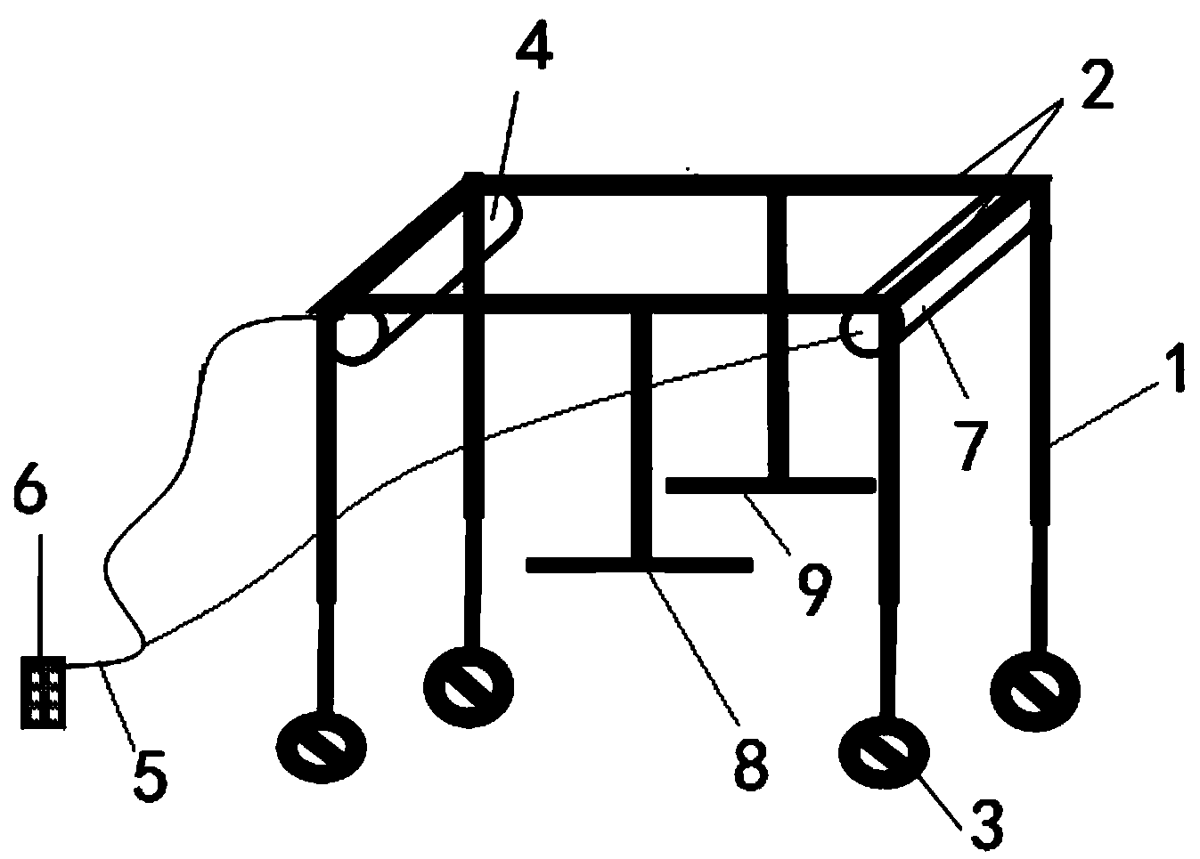
[0025] Such as figure 1 , figure 2 Shown, a kind of movable parking frame that is used for parking the car in the flat parking lot, the car hoist is made up of the first car lifting frame 8, the second lifting frame 9, the first car lifting frame 8, the second lifting frame 9 are respectively connected The beams 2 on both sides of the tire-type double-frame gantry crane; the four wheels 3 of the tire-type double-frame gantry crane are respectively connected to four columns 1, and the four columns 1 are connected to the beam 2 respectively, and the front beam 2 is connected to the first motor unit 4 , the crossbeam 2 on the rear side is connected to the second motor unit 7, and the first motor unit 4 and the second motor unit 7 are connected to the control panel 6 through the ...

Embodiment 2

[0030] Embodiment 2: A method for using a movable parking rack for parking cars in a flat parking lot, the steps are as follows:

[0031] Step 1. Expand the parking frame to a width and length larger than that of a car;

[0032] Step 2. Move the parking rack directly above the car that needs to be moved or adjusted;

[0033] Step 3. Put down the car lifting frame to lift the car off the ground and higher than other cars, drive the parking frame to a suitable position, and put down the car to the correct parking space.

[0034] Step 4, the parking frame puts away the lifting frame and leaves the car that has been placed.

Embodiment 3

[0035] Embodiment 3: A method of using a movable parking rack for parking cars in flat parking lots,

[0036] Step one, step two are the same as embodiment 1,

[0037] Step 3. Put down the car lifting frame and lift the car off the ground higher than other cars, which is convenient for maintenance personnel to check and repair the car from below.


PUM


Abstract

The invention discloses a movable parking frame for parking cars in a flat parking lot and a using method, and belongs to the technical field of civil machines. A car elevator is connected with beams on the two sides of a rubber-tyred double-frame gantry crane. Four wheels of the rubber-tyred double-frame gantry crane are connected with four stand columns respectively. The four stand columns are connected with the four beams. A motor set is installed on the beams. The motor set is connected with a control panel through a cable. The control panel controls the frame to operate. The movable parking frame has the advantages of being capable of moving to the portion over the cars at any time to freely carry the parked cars or adjust the positions of the cars so as to achieve the best parking effect, capable of being extended, widened and heightened so as to be suitable for different working requirements, and capable of moving to the parking positions of the cars at any time to lift the cars so as to achieve the purpose that a car maintenance worker on the site inspects and maintains the cars below the cars.

Description

technical field [0001] The invention relates to a movable parking frame for parking cars in a flat parking lot and a using method thereof, belonging to the technical field of civil machinery. Background technique [0002] Some residential areas have tight parking spaces, but the upper floors of the existing parking spaces are idle. At present, the parking of cars in the flat parking lot can only be realized by the movement of the car itself. The driver's operating level has a great influence on the occupancy of the parking space, and once the wrong position is parked, it will hinder the traffic in the field until the owner is waiting or driving. Only when the person arrives can it be resolved. Contents of the invention [0003] Utilizing the upper space of the existing parking space for parking and overcoming the problem that cars are not neatly placed after parking, the invention provides a movable parking frame for parking cars in a flat parking lot and a usage method. ...

Claims


Application Information

Patent Timeline
Patent Type & Authority Applications(China)
IPC IPC(8): E04H6/06E04H6/04E04H6/18
Inventor 高善一
Owner 高善一
Why Eureka
Eureka Blog
Learn More