
Test device for simulating continuous punching shear loading

A test device and impact load technology, applied in the field of geotechnical engineering and geotechnical mechanics, can solve the huge difference in the ability to withstand dynamic load impact, the shear strength of the shear plane has a great influence, and the change of the shear plane strength is difficult to measure and other problems, to achieve the effect of compact device structure, convenient strength change and convenient application

Inactive Publication Date: 2014-04-16
HOHAI UNIV
View PDF4 Cites 13 Cited by
  • Summary
  • Abstract
  • Description
  • Claims
  • Application Information

AI Technical Summary

Problems solved by technology

[0003] In practice, the strength of rock and soil under dynamic load is significantly different from that under static load. Even if the dynamic load is small, when the load has a certain rate of change, the ability of the shear surface of rock and soil to withstand the impact of dynamic load varies greatly. , but the strength change of the shear surface under dynamic punching shear is difficult to measure, because it is difficult to obtain continuous punching shear load in direct shear test
[0004] In particular, for soil-rock mixed media cemented by granular media, particle differences and the complexity of the shear plane have a great influence on the shear strength of the shear plane. There is no dynamic shear strength test for this type of media in the current test regulations. Therefore, the development of continuous impact shear test method has good engineering practice value

Method used


Image

  • Test device for simulating continuous punching shear loading
  • Test device for simulating continuous punching shear loading
  • Test device for simulating continuous punching shear loading

Examples


Embodiment

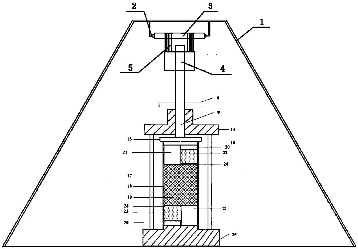
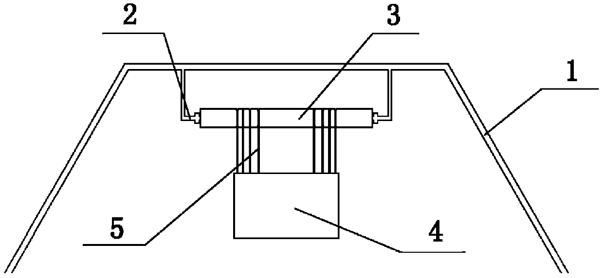
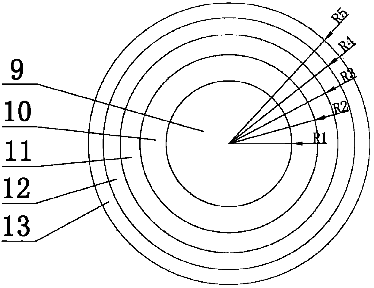
[0019] Embodiment: a kind of test device for simulating continuous impact shear loading, such as figure 1 As shown, including impact load mechanism and sample punching and shearing mechanism, impact load mechanism (such as figure 2 shown) includes steel truss 1, roller support 2, roller 3, drop weight 4, rope 5, cover plate 6 and center column 9, center column 9 passes through cover plate 6 longitudinally and is fixed, drop weight 4 consists of four 10; 11; 12; 13 are composed of collars 10; 11; 12; 13 whose radii increase sequentially but are equal in quality, and are nested on the top of the central column 9 from large to small, such as image 3 As shown, the outer diameter of the inner collar 10; 11; 12; 13 between two adjacent collars 10; 11; 12; 13 is equal to the inner diameter of the outer collar 10; 11; 12; 13, The central column 9 is a cylinder with a section radius of R1, the section of the collar 10; 11; 12; 13 is a ring, the inner and outer radii of the collar 10...


PUM


Abstract

The invention discloses a test device for simulating continuous punching shear loading. An impact loading mechanism comprises a central post, a drop hammer, a rope and a cover plate, wherein the drop hammer comprises a group of lantern rings which are nested at the top of the central post, the radiuses of the lantern rings gradually increase, the lantern rings are suspended by the rope, and the cover plate is fixed in such a way that the central post penetrates through the center of the cover plate. A sample punching shear mechanism is a pressure chamber which is arranged at the lower part of the impact loading mechanism, a sample cavity which is coated with a rubber film cover is arranged in the pressure chamber, and an upper shear box and a lower shear box are respectively arranged at the upper part and the lower part of the sample cavity in the rubber film cover. Axial force is converted to shear force by a difference between the rigidity of a shear block and the rigidity of a deformation block in the shear device, and a test function of directly shearing a sample vertically is realized. A shear plane is determined, and convenience in shear loading and positive pressure application is instrumental to the measurement of the variation of the strength of the sample under punching shear action. All the solid rings in the device are equal in mass. Impact energy can be effectively controlled through the control of drop heights, so that the mechanical parameters, such as shear, of the sample under dynamically loaded action can be accurately determined.

Description

technical field [0001] The invention relates to the fields of rock and soil mechanics and geotechnical engineering, in particular to a device for testing the shear surface strength of a sample under the condition of continuous dynamic load punching and shearing. Background technique [0002] In the field of geotechnical engineering, shear failure of rock and soil is a common form of failure, and after the shear surface is formed, the strength index and mechanical properties of the shear surface are important indicators for calculating the stability of rock and soil. The shear test is the main technical means and method to obtain the basic mechanical parameters of rock and soil. [0003] In practice, the strength of rock and soil under dynamic load is significantly different from that under static load. Even if the dynamic load is small, when the load has a certain rate of change, the ability of the shear surface of rock and soil to withstand the impact of dynamic load varies...

Claims


Application Information

Patent Timeline
IPC IPC(8): G01N3/34G01N3/24
Inventor 石崇李德杰王芳陈凯华徐卫亚王海礼张玉龙王秀菊朱其志孙怀昆
Owner HOHAI UNIV
Learn More