A Microwave Fluid Medium Detector

A fluid medium and microwave medium technology, applied in the field of microwave detectors, can solve the problem of not publicly measuring the dielectric constant of fluids and the like

Active Publication Date: 2015-12-02
浙江海牛海洋工程有限公司
View PDF6 Cites 0 Cited by
  • Summary
  • Abstract
  • Description
  • Claims
  • Application Information

AI Technical Summary

Problems solved by technology

In the practical application of microwave, the dielectric constant of the medium can generally be measured by microwave transmission line or microwave resonator, but this method has been generally used in the field of electronics. Apparatus for measuring the dielectric constant of fluids

Method used


Image

  • A Microwave Fluid Medium Detector
  • A Microwave Fluid Medium Detector
  • A Microwave Fluid Medium Detector

Examples


specific Embodiment 1

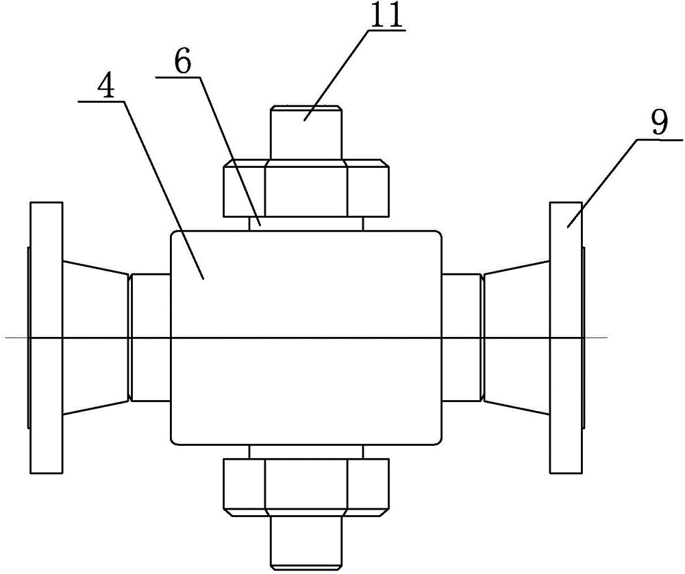
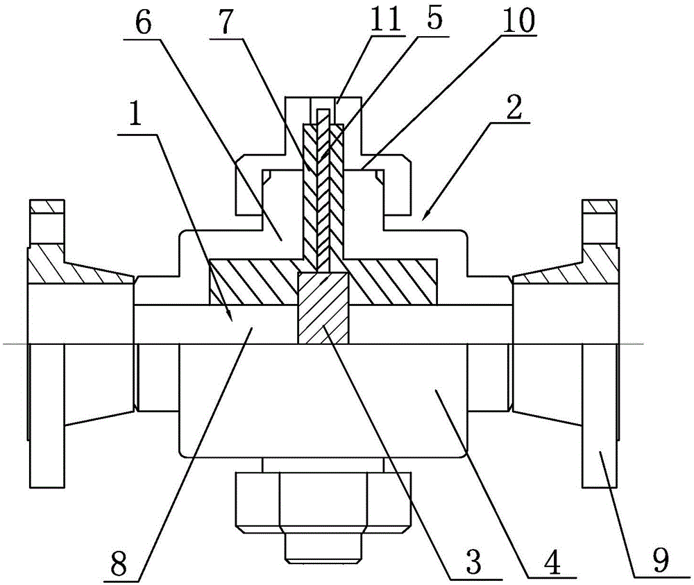
[0022] A microwave fluid medium detector, such as figure 2 , image 3 and Figure 4As shown, it includes a microwave transmission line. The microwave transmission line includes an open microwave transmission line 1 in the middle section and a closed microwave transmission line 2 on both sides. A first outer conductor 4 coaxial with an inner conductor 3, the enclosed microwave transmission line 2 includes a second inner conductor 5, a second outer conductor 6 sheathed on the outer periphery of the second inner conductor 5 and coaxial with the second inner conductor 5, and The low-loss microwave medium 7 is sealed and filled between the second inner conductor 5 and the second outer conductor 6, the second inner conductor 5 on both sides is connected with the first inner conductor 3 in the middle in a straight line, and the second outer conductor 6 on both sides is connected to the middle The first outer conductor 4 is integrally connected and forms a water flow through hole 8...

specific Embodiment 2

[0024] A microwave fluid medium detector, such as figure 2 , Figure 5 and Figure 6 As shown, it includes a microwave transmission line. The microwave transmission line includes an open microwave transmission line 1 in the middle section and a closed microwave transmission line 2 on both sides. A first outer conductor 4 coaxial with an inner conductor 3, the enclosed microwave transmission line 2 includes a second inner conductor 5, a second outer conductor 6 sheathed on the outer periphery of the second inner conductor 5 and coaxial with the second inner conductor 5, and The low-loss microwave medium 7 is sealed and filled between the second inner conductor 5 and the second outer conductor 6, the second inner conductor 5 on both sides is connected with the first inner conductor 3 in the middle in a straight line, and the second outer conductor 6 on both sides is connected to the middle The first outer conductor 4 is integrally connected and forms a water flow through hole...


PUM


Abstract

The invention discloses a microwave fluid medium detector. The microwave fluid medium detector is characterized by comprising a microwave transmission line, wherein the microwave transmission line comprises an open-middle-type microwave transmission line and a two-sealed-side-type microwave transmission line; the open-type microwave transmission line comprises a first inner conductor and a first outer conductor; the sealed-type microwave transmission line comprises second inner conductors, second outer conductors and a low-loss microwave medium; the second inner conductors at two sides and the first inner conductor in the middle are connected in a linear mode; the second outer conductors at two sides and the first outer conductor in the middle are integrally connected and mutually form water flow through holes; openings in two ends of the water flow through holes are connected with pipelines through which the to-be-detected fluid medium flows by flanges; the fluid flowing direction of the water flow through holes is mutually perpendicular to the axial direction of the first inner conductor; coaxial wire ports formed by end parts of the second outer conductors and the second inner conductors are connected with a microwave adapter; the microwave adapter is connected with an external microwave measurement device. The microwave fluid medium detector has the advantages that structure is simple, operation is convenient, and the fluid medium can be measured continuously online.

Description

technical field [0001] The invention relates to a microwave detector, in particular to a detector capable of measuring medium parameters of fluid in pipelines in radio frequency and microwave frequency bands. Background technique [0002] In the field of petrochemical industry, it is often necessary to measure the content of various components of the mixed fluid in the pipeline, and the measurement method often uses the difference in certain physical properties of different components, so that the mixing ratio of the components is not related to these physical properties at the same time The parameters of will change accordingly, and the mixing ratio of components can be deduced by measuring this parameter. For example, if there is a mixed flow of oil and water in the pipeline, under normal circumstances, the density of oil and water is different, and oil is lighter than water. When the mixing ratio of oil and water is different, the density of the oil-water mixture will cha...

Claims


Application Information

Patent Timeline
Patent Type & Authority Patents(China)
IPC IPC(8): G01N22/00G01R27/26
Inventor 徐耀忠冯福祥王建荣
Owner 浙江海牛海洋工程有限公司
Why Eureka
Try Eureka