Sound signal adjustment apparatus and method, and telephone

a technology of sound signal and adjustment apparatus, which is applied in the direction of gain control, electrical transducers, substation equipment, etc., can solve the problems of volume control problems, the voice of both parties in the telephone conversation may therefore become difficult to hear, and the portable telephone has become extremely small, so as to achieve convenient, practical and low-cost

Inactive Publication Date: 2010-07-22
OKI ELECTRIC IND CO LTD
View PDF4 Cites 46 Cited by
  • Summary
  • Abstract
  • Description
  • Claims
  • Application Information

AI Technical Summary

Benefits of technology

[0022]An object of the present invention is to provide a convenient, practical, and low-cost apparatus and method for adjusting a sound signal in a telephone.

Problems solved by technology

Often they are used in speaking and listening environments that are inferior to the environments in which landline outdoor telephones are used.
The voices of both parties in the telephone conversation may therefore become hard to hear because of ambient noise.
Because of the primary need for portability, however, portable telephones have become extremely small.
This leads to volume control problems, because often the user of a portable telephone does not realize that the volume setting of the telephone's speaker is too low until after the conversation has begun.
To adjust the volume to the proper level, the user must operate the manual volume control, but with today's downsized telephones it is difficult to find the volume control by touch alone.
With the increasing number of functions being built into modern portable phones, there is also the risk of operating the wrong control by mistake and activating an unintended function.
The distant party may suspect that the user simply was not paying attention or had lost interest in the conversation, resulting in damage to personal relations between the two parties.
The equipment uses the microphone to detect the magnitude of ambient noise, and increases the speaker volume in noisy environments.
In the context of today's portable telephones, all of the above disclosures are problematic.
The decreasing size leaves little room for additional sensors.
For example, it is difficult to find space in which to embed the pressure sensor required by JP 2005-20730.
The method disclosed in JP H01-241208 of controlling speaker volume according to the ambient noise level detected by a microphone could in theory be applied to a portable telephone to adjust the speaker volume without requiring an additional sensor, but this method fails to meet all the requirements of a portable telephone.
For example, it fails when the user wants to increase the speaker volume, not because of ambient noise, but because the distant party is speaking in a small voice.
A more basic problem is that if the user did press a portable telephone against his or her ear in order to hear the distant party's voice better, JP H07-038624 would respond by decreasing the speaker volume, making the distant party's voice even harder to hear.
A problem is that the user may be using the portable telephone in a quiet environment and may want to increase the speaker volume because the distant party is talking in a small voice.
In this case the user may hesitate to raise his or her own voice because that would disturb other people nearby.
A more subtle problem is that, since the portable telephone does not distinguish between the user's voice and ambient noise, the speaker volume is automatically increased in response to ambient noise in a noisy environment.
As a result, the distant party has difficulty hearing the user's voice over the ambient noise.
A problem with JP 2008-187221 is that in almost all camera-equipped portable telephones, the camera is not mounted on the same surface as the display screen; it is mounted on the opposite surface and points away from the user's head.
Even in portable telephones with two cameras, front and back, there is the problem that use in a dark environment can cause an unwanted switchover from the hands-free speaker to the ear speaker even though the telephone is distant from the user's head.
Furthermore, this camera-based method only provides a way of switching from one speaker to another; it does not provide a method of adjusting the volume of a speaker.
A problem with the spectral subtraction method of JP 2007-116585 is that it does not work well when a microphone is carried from one location to another location with a different ambient noise pattern, a frequent occurrence with portable telephones.

Method used


Image

  • Sound signal adjustment apparatus and method, and telephone
  • Sound signal adjustment apparatus and method, and telephone
  • Sound signal adjustment apparatus and method, and telephone

Examples


first embodiment

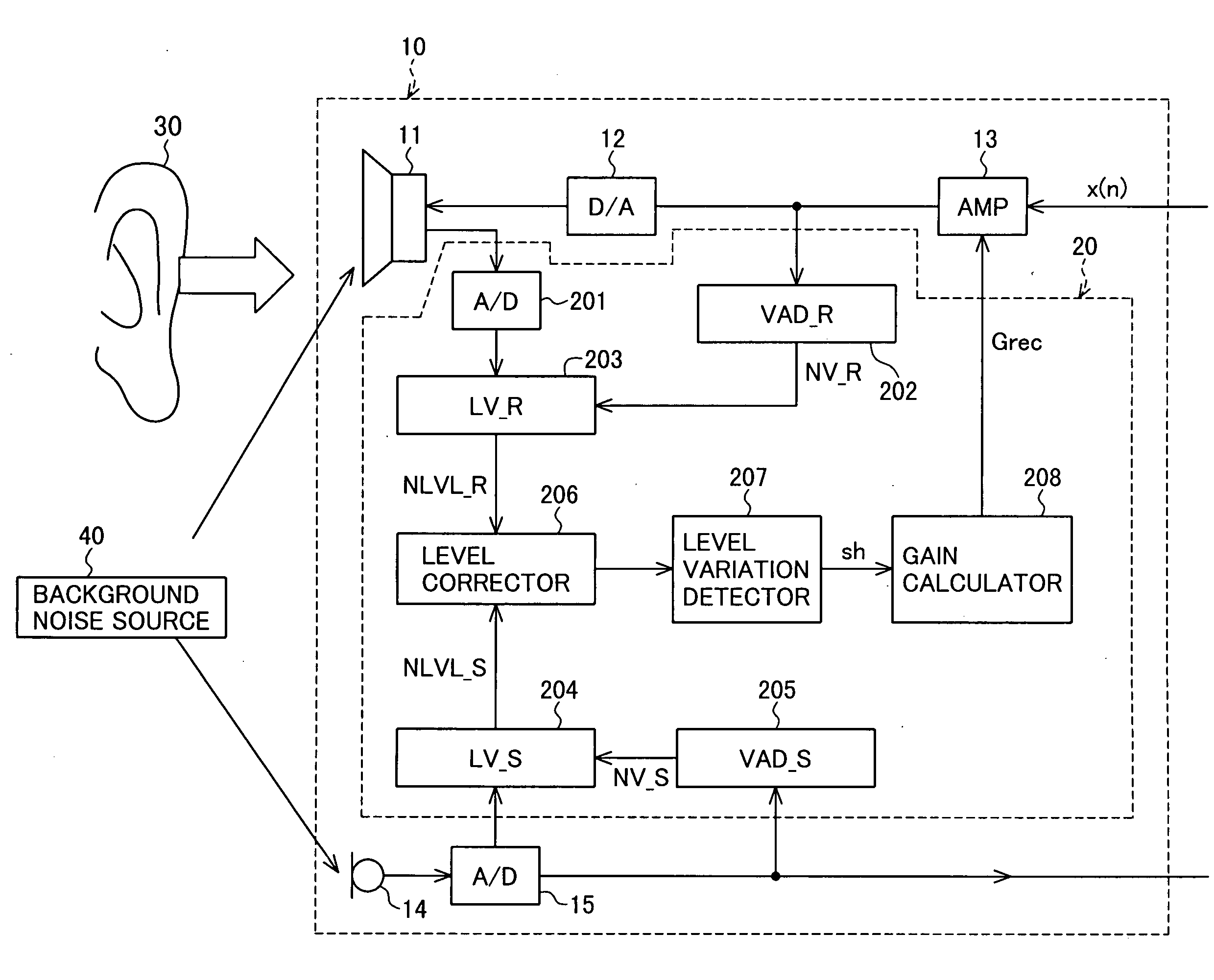
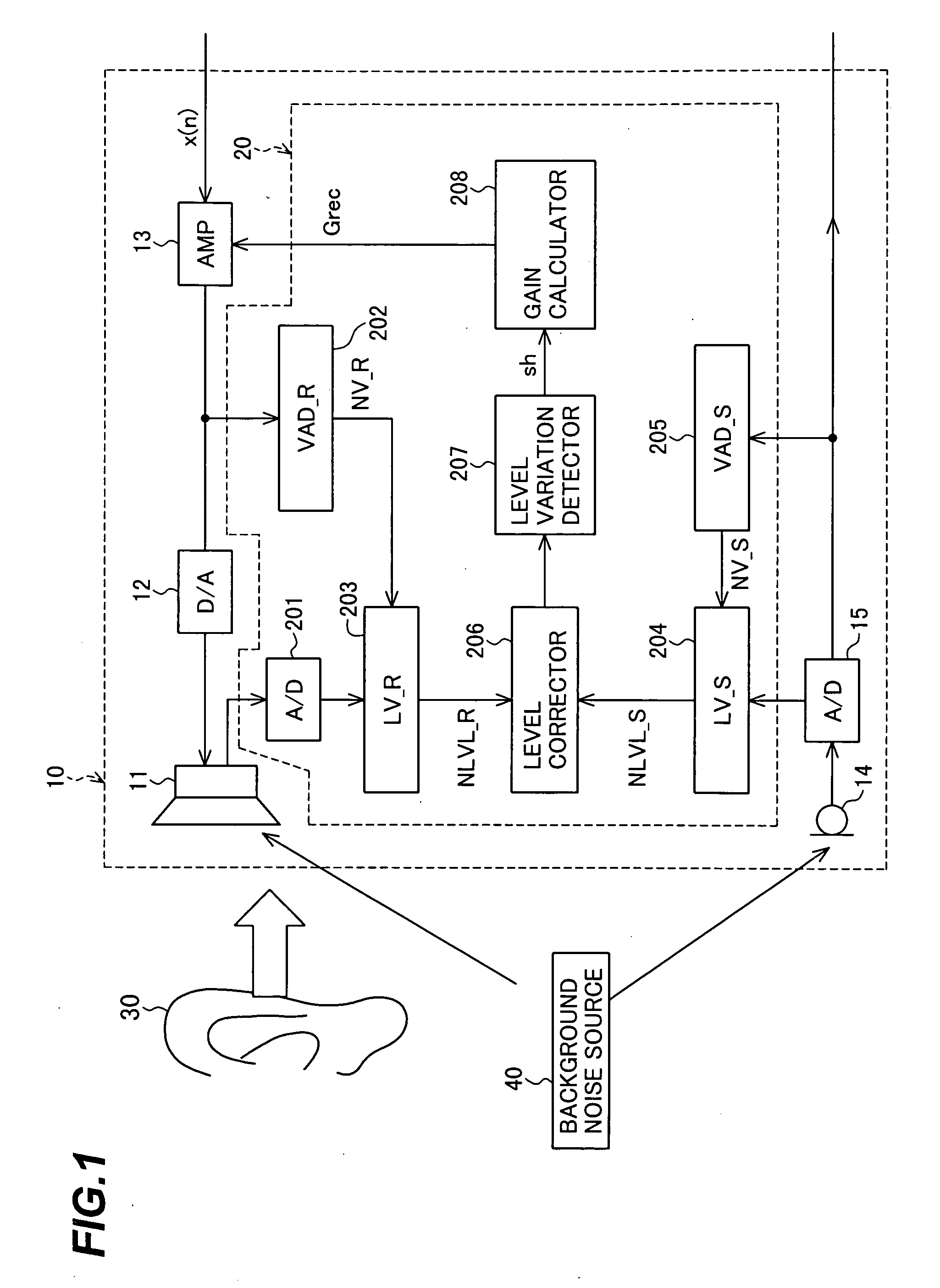
[0051]Referring to the block diagram in FIG. 1, the first embodiment is a telephone 10 including an ear speaker referred to below simply as a speaker 11, a digital-to-analog converter (DAC) 12, an amplifier (AMP) 13, a microphone 14, an analog-to-digital converter (ADC) 15, a sound signal adjustment apparatus 20, and numerous well-known elements, including pushbuttons and other manual controls, which are not shown.

[0052]The telephone 10 receives a far end signal x(n) from a distant party (not shown), reproduces it for the user (whose ear 30 is shown), picks up the user's voice, and transmits the user's voice to the distant party.

[0053]More specifically, when the user (also referred to below as the near end party) speaks into the microphone 14, the microphone 14 converts the user's voice to an analog electrical signal, which is converted to a digital signal by ADC 15 and transmitted as a near end signal to the distant party (also referred to below as the far end party).

[0054]The far ...

second embodiment

[0090]Referring to the block diagram in FIG. 5, the telephone 10A in the second embodiment differs from the first embodiment by including a modified sound signal adjustment apparatus 20A having a modified level variation detector 207A and a modified gain calculator 208A.

[0091]When condition (4) is true and condition (5) is false, differing from the level variation detector 207 in the first embodiment, the level variation detector 207A calculates a quantity Dif_lev_r by the following equation (6), and supplies the value of Dif_lev_r, instead of the detection signal sh, to the gain calculator 208A.

Dif_lev—r=NLVL—R—r2−NLVL—R—r1  (6)

[0092]The gain calculator 208A multiplies the value of Dif_lev_r by a parameter δ20 as in the following equation (7) to calculate a gain value (Grec) for the amplifier 13.

Grec=δ20×Dif_lev—r  (7)

[0093]The parameter δ20 in equation (7) may have the value 2.0 (δ20=2.0). The amplifier 13 amplifies the far end signal x(n) by the gain calculated in the gain calcul...

third embodiment

[0097]Referring to the block diagram in FIG. 6, the telephone 10B in the third embodiment differs from the second embodiment by including a modified sound signal adjustment apparatus 20B having a modified receiving voice activity detector 202B inserted between the DAC 12 and the amplifier 13.

[0098]The modified receiving voice activity detector 202B in the third embodiment detects voice activity in the far end signal in the same way as in the first and second embodiments. The difference between the third embodiment and the first and second embodiments is that when voice activity is detected in the far end signal received from the amplifier 13, the receiving voice activity detector 202B supplies the far end signal to the DAC 12, but when no voice activity is detected in the far end signal, the receiving voice activity detector 202B stops supplying the far end signal to the DAC 12.

[0099]Although the sound signal adjustment apparatus 20B shown in FIG. 6 is a modification of the sound si...


PUM


Abstract

A telephone with a speaker and a microphone uses the speaker both as an electric-to-acoustic transducer, to reproduce the far end party's voice, and an acoustic-to-electric transducer, to capture external sound in the vicinity of the near end party. From the captured sound signal and the signal picked up by the microphone, a decision unit decides whether or not the external sound is being blocked. When the external sound is blocked, a volume control unit increases the volume of the far end party's voice as reproduced by the speaker. The near end party can accordingly turn up the speaker volume by moving the part of the telephone including the speaker close to the user's ear to block external sound, without having to manipulate any manual controls.

Description

BACKGROUND OF THE INVENTION[0001]1. Field of the Invention[0002]The present invention relates to a sound signal adjustment apparatus and method and a telephone such as a portable telephone.[0003]2. Description of the Related Art[0004]By their nature, portable telephones are used under a wide variety of ambient conditions, frequently outdoors. Often they are used in speaking and listening environments that are inferior to the environments in which landline outdoor telephones are used.[0005]For example, portable telephones are usually used in an exposed environment, rather than an enclosed environment such as a telephone booth. The voices of both parties in the telephone conversation may therefore become hard to hear because of ambient noise. The user can cope with this situation by turning up the volume of the telephone set.[0006]Because of the primary need for portability, however, portable telephones have become extremely small. The buttons and other manual controls of a modern por...

Claims


Application Information

Patent Timeline
Patent Type & Authority Applications(United States)
IPC IPC(8): H03G3/00H04M1/00
CPCH04M9/082H04R3/00
Inventor TAKADA, MASASHI
Owner OKI ELECTRIC IND CO LTD
Why Eureka
Try Eureka