Ornamental module and ornament device thereof

Inactive Publication Date: 2011-09-29
CHEUNG BANLY
View PDF1 Cites 46 Cited by
  • Summary
  • Abstract
  • Description
  • Claims
  • Application Information

AI Technical Summary

Benefits of technology

[0022]To implement the ornament module and the ornament device thereof according to the present invention, ornament module in static state, especially the ornament device comprising a plurality of ornament modules, can be arranged in different three-dimensional shapes to achieve static visual effect, or, to start motivity unit, each ornament module will make a telescopic mechanical movement individually under the control of the mater computer, as a result, a plurality of ornament units provided on the top of the ornament module will form a three-dimensional moving surface to achieve a dynamic three-dimensional visual effect. If the ornament units are LED display modules and are supplemented by a display control unit, t

Problems solved by technology

Existing ornament appliances, such as sculptures or the like, which only have a static stereoscopic visual effect, and, when at night, their ornamental effect will be very limited in the absence of illumination.
Existing ornament appliances, such as spotlights or the like, which can be brought into play a static or dynamic lighting ornamental effect at night or in weak light environments, but have a limited role in the daytime.
Existing ornament appliances, such as LCD or LED display, which have planar ornamental effe

Method used


Image

  • Ornamental module and ornament device thereof
  • Ornamental module and ornament device thereof
  • Ornamental module and ornament device thereof

Examples


embodiment one

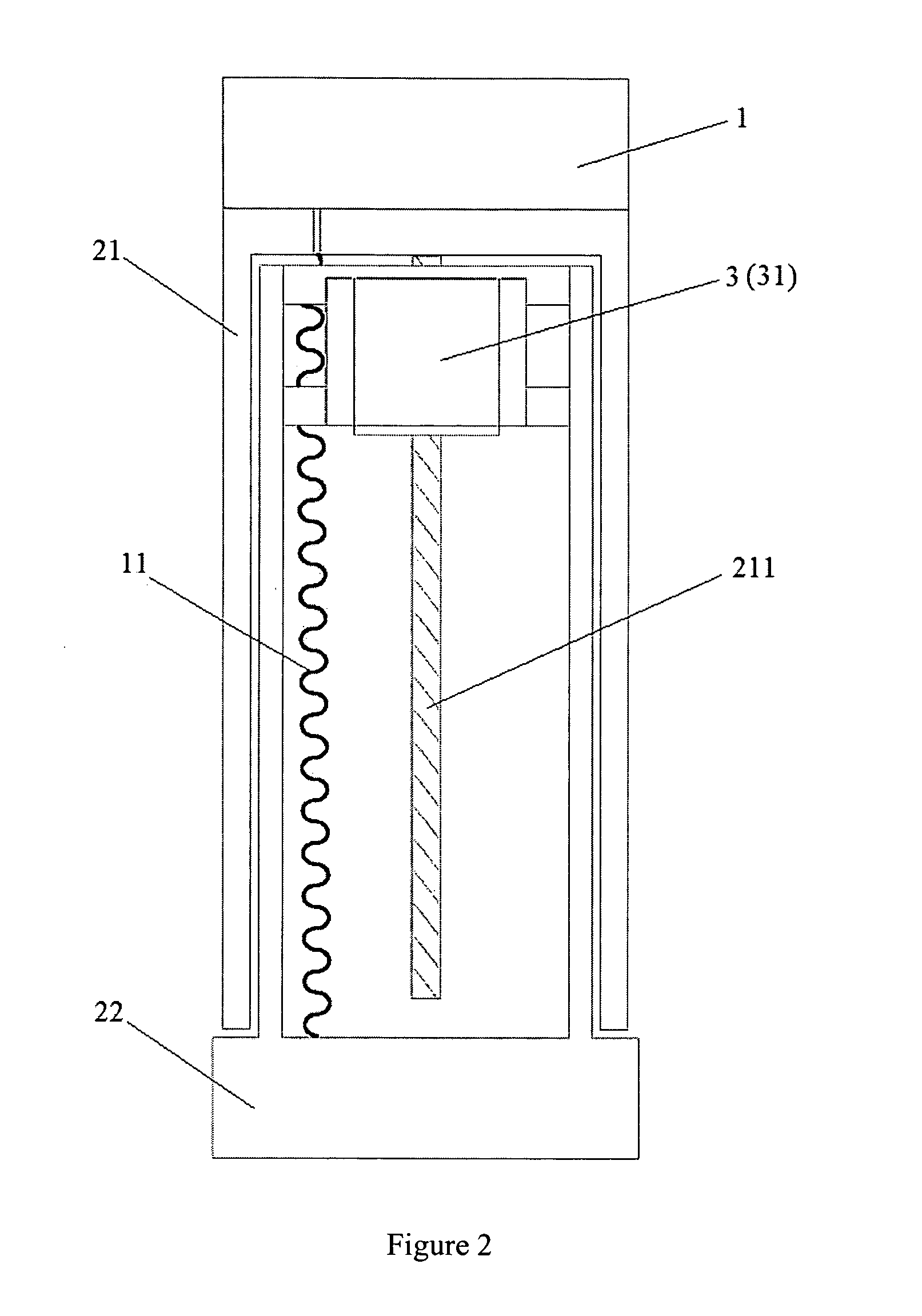
[0039]As shown in FIG. 2, the mechanical movement unit of the ornament module with a cylinder-type structure, includes a hollow columnar shell 21, a hollow base 22 set within the shell cavity, as well as a transmission screw 221 connecting fixedly to the top of the shell cavity and extending into the hollow space of the base along the axial direction of the columnar shell, the shell 21 can move up or down mechanically along the base 22, this mechanical movement is started by a motivity unit 3, the motivity unit 3 is a linear motor 33 set fixedly within the hollow space of the base and screwed to the transmission screw 211, then when the motor is forward or reverse, it will drive the transmission screw 211 to move up or down telescopically, and the transmission screw drive the shell to move up or down mechanically along the base. If the motivity control unit is a frequency converter that will further control the speed of the motor, the shell 21 make a up or down motion along the base...

embodiment two

[0044]As FIG. 7 shows, the mechanical movement unit of the ornament module with a cylinder-type structure, includes a hollow columnar shell 21, a hollow base 22 set within the shell cavity, as well as a transmission thread insert 212 connecting fixedly to the top of said shell cavity and extending into the hollow space of said base along the axial direction of said columnar shell, the shell 21 can move up or down mechanically along the base 22, the mechanical movement is started by the motivity unit 3, the motivity unit 3 is a rotating motor 31 set fixedly within the hollow space of the base, the rotating motor 31 is connected fixedly with a transmission screw 212 screwed to the transmission thread insert 212, then when the motor is forward or reverse, it will drive the transmission screw 213 to rotate, and the transmission screw drive the transmission thread insert 212 to move up or down telescopically, namely the shell move up or down mechanically along the base. If the motivity c...

embodiment three

[0046]As shown in FIG. 8, the mechanical movement unit of the ornament module with a cylinder-type structure, includes a hollow columnar shell 21, a hollow base 22 set within the shell cavity, as well as a pressure uplift device 221 set within the hollow space of said base. The shell 21 can move up or down mechanically along the base 22. The top of said pressure uplift device 221 is against the top of said shell 21 cavity closely, the bottom of said pressure uplift device 221 is against the bottom of the hollow space of said base 22, the ornament unit 1 is provided on the top of said columnar shell 21, the motivity unit is a pneumatic engine 32 (shown in FIG. 9) set at the external of mechanical movement unit for supplying said pressure uplift device. As shown in FIG. 8, there is a cable 11 integrated with data and power through the top end of the columnar shell 21 to connect with the ornament unit 1. As shown in FIG. 9, as a motivity control unit, an electronically controlled pneum...


PUM


Abstract

The present invention discloses an ornament module with a column structure, which comprises a ornament unit provided on the top of the column structure, a mechanical movement unit connecting to the ornament unit and making the ornament unit move, a motivity unit driving the mechanical movement unit, and a motivity control unit connecting to the motivity unit and controlling the operation of the motivity unit. The present invention also discloses an ornament device which comprises two or more ornament modules, a master computer and a distributed control unit. The distributed control unit is connected to the motivity control unit of each ornament module on one end and connected to the master computer on the other end. To implement the ornament module and the ornament device thereof according to the present invention, their ornamental effects give consideration to application of static and dynamic, planar and stereoscopic, day and night, which can be a fixed setting or a mobile setting, and have good practicability.

Description

FIELD OF THE INVENTION[0001]The present invention relates to ornament appliance, specifically relates to ornament module and ornament device thereof.BACKGROUND OF THE INVENTION[0002]Ornament appliance is common item in modern society, a variety of temporary or fixed-set ornament appliances often can be seen in the exhibition, commercial plaza, gymnasium or the like.[0003]Existing ornament appliances, such as sculptures or the like, which only have a static stereoscopic visual effect, and, when at night, their ornamental effect will be very limited in the absence of illumination.[0004]Existing ornament appliances, such as spotlights or the like, which can be brought into play a static or dynamic lighting ornamental effect at night or in weak light environments, but have a limited role in the daytime.[0005]Existing ornament appliances, such as LCD or LED display, which have planar ornamental effect of playing video, but are lack of ornamental effect of dynamic motion and stereoscopic ...

Claims


Application Information

Patent Timeline
IPC IPC(8): F21V33/00A47G35/00F15B21/00
CPCG06F1/182G09F9/33Y10T428/2913G09F9/377Y10T428/2973G09F9/372
Inventor CHEUNG, BANLY
Owner CHEUNG BANLY
Why Eureka
Try Eureka