Defense method for commutation failures of direct-current transmission based on current limiting method

A commutation failure, DC transmission technology, applied in the field of power transmission and distribution, can solve the problems of increasing the power factor of the AC fault DC current DC transmission system, reducing the power factor of the DC transmission system, and being unfavorable for the restoration of the commutation bus voltage. Achieve the effects of reducing secondary commutation failure, reducing the probability of commutation failure, and reducing the commutation area

Active Publication Date: 2014-04-16
NORTH CHINA ELECTRIC POWER UNIV (BAODING) +3
View PDF5 Cites 15 Cited by
  • Summary
  • Abstract
  • Description
  • Claims
  • Application Information

AI Technical Summary

Problems solved by technology

[0031] Increasing β (that is, triggering in advance) will make the inverter side DC voltage U d2 drop, DC current I dc It shows an upward trend, which is not conducive to the commutation of thyristors; and when β increases, the power factor of the DC transmission system decreases, which is not conducive to the recovery of the commutation bus voltage
[0032] In summary, the existing defense methods have a certain effect on the DC transmission system against commutation failures, but will increase the DC current during the AC fault process and reduce the power factor of the DC transmission system, which may sometimes lead to negative results

Method used


Image

  • Defense method for commutation failures of direct-current transmission based on current limiting method
  • Defense method for commutation failures of direct-current transmission based on current limiting method
  • Defense method for commutation failures of direct-current transmission based on current limiting method

Examples


Embodiment Construction

[0063] The specific embodiments of the present invention will be further described in detail below in conjunction with the accompanying drawings.

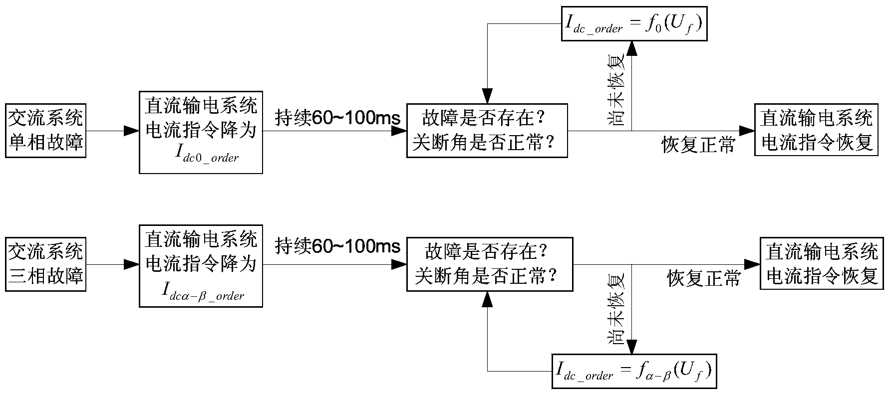
[0064] Such as figure 1 as shown, figure 1 It is the implementation flowchart of the DC transmission commutation failure defense method based on the current limitation method; among the figure, I dc0_order When a single-phase fault is detected, the current command immediately reduces to the value; I dcα-β_order When a three-phase fault is detected, the current command immediately decreases to the value; I dc_order After the current command decreases and lasts for a period of time (60~100ms), and the fault has not been cleared or the cut-off angle has not returned to normal, the current command is calculated from the effective value of the line voltage of the commutation bus; U f is the effective value of the line voltage of the commutation bus, the unit is p.u.; f 0 (), f α-β () respectively indicate that when a single-phase f...


PUM


Abstract

The invention provides a defense method for commutation failures of direct-current transmission based on a current limiting method. The method comprises the following steps: I, according to an output signal of failure detection, detecting the failure type of a commutation bus of a direct-current transmission system; II, by using the current limiting method, reducing a direct-current instruction and continuing for 60-100 ms; III, judging whether a failure is eliminated and a turn-off angle of the direct-current transmission system is restored; and IV, determining the direct-current instruction according to a judgment result until the failure is eliminated, and restoring the direct-current instruction. According to the method, adverse effects such as increasing a direct-current, increasing a power factor angle of the direct-current transmission system, and the like caused by advanced triggering are avoided, and a timely and effective response is made to an alternating-current system failure, so that the required commutation area of a thyristor is reduced, thereby facilitating that the direct-current transmission system is prevented from having commutation failures.

Description

technical field [0001] The invention relates to a method in the technical field of power transmission and distribution, in particular to a method for preventing commutation failure of direct current transmission based on fast current limitation. Background technique [0002] Since the 1950s, the traditional line-commutated-converter high-voltage direct current (LCC-HVDC) has gained rapid popularity worldwide due to its large-capacity long-distance power transmission and fast controllable active power. development of. [0003] However, since LCC-HVDC uses ordinary thyristors without self-shutoff capability as commutation components, the LCC-HVDC system requires a certain strength of the AC system to achieve commutation, and the commutation voltage needs to be provided by the AC grid. When the power grid fails or the three-phase is seriously asymmetrical, the AC bus voltage will drop, the line voltage zero crossing point may be advanced, the commutation overlap angle of the L...

Claims


Application Information

Patent Timeline
Patent Type & Authority Applications(China)
IPC IPC(8): H02J3/36G01R31/08
CPCY02E60/60Y04S10/522Y04S10/52
Inventor 郭春义刘羽超赵成勇李春华许韦华阳岳希
Owner NORTH CHINA ELECTRIC POWER UNIV (BAODING)
Why Eureka
Try Eureka