Crystal boat

A technology of wafers and elastic parts, applied in the field of locking structures of wafer boats, can solve problems affecting product yield, product scrapping, and a large number of metal particles

Active Publication Date: 2014-04-23
CHIPMORE TECH CORP LTD
View PDF5 Cites 4 Cited by
  • Summary
  • Abstract
  • Description
  • Claims
  • Application Information

AI Technical Summary

Problems solved by technology

[0005] The bars are composed of M-shaped steel wires and springs. During the operation, personnel are required to manually switch the bars. If the personnel forget to close the bars, serious problems such as product scrapping will be caused due to the wafer slipping out during the lifting of the wafer boat.
[0006] When the steel rail is used, it will rub against the wafer itself, producing a large amount of metal particles, which will affect the yield of the product

Method used


Image

  • Crystal boat
  • Crystal boat
  • Crystal boat

Examples


Embodiment Construction

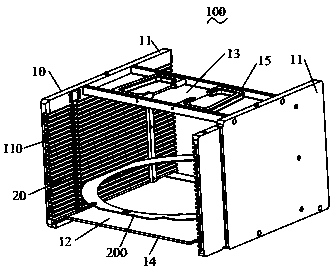
[0032] Such as Figure 1-13 As shown, the wafer boat 100 of the present invention is used for accommodating wafers 200 and can be placed on the horizontal surface of a working platform (not shown). The wafer boat 100 includes a main body 10 , a bar 20 installed on the main body 10 , and an automatic locking component 30 installed on the main body 10 .

[0033] Such as figure 1 and 2 As shown, the main body 10 includes a pair of sidewalls 11 arranged at intervals, a storage space 12 between the pair of sidewalls 11 for accommodating the wafer 200 , and a horizontally arranged top wall connecting the pair of sidewalls 11 13 , and a bottom wall 14 arranged parallel to the top wall 13 at intervals and connecting the pair of side walls 11 . A handle 15 is disposed on the top wall 14 .

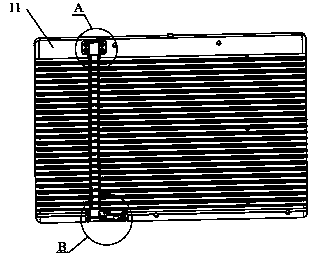
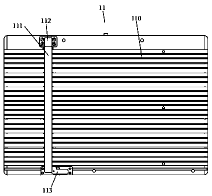
[0034] Such as Figure 1-3 As shown, the pair of side walls 11 are vertically arranged, and each side wall 11 is provided with a plurality of storage tanks 110 arranged at intervals horizontall...


PUM


Abstract

The invention discloses a crystal boat comprising a main body portion and a block bar. The main body portion includes a pair of side walls that are arranged at an interval; a plurality of accommodation grooves that are arranged horizontally at intervals are respectively arranged at the pair of side walls; and two ends of a wafer are respectively accommodated into the accommodation grooves of the corresponding side walls and can slide along the accommodation grooves. An installation groove perpendicular to the accommodation grooves is arranged at one side wall and the block bar is installed in the installation groove; and a plurality of slotting units corresponding to the accommodation grooves are arranged at the block bar. The block bar can move between a starting position and a locking position; at the starting position, the slotting units are communicated with the accommodation grooves and the wafer can pass by; and at the locking position, the slotting units and the accommodation grooves are in a staggered mode and thus the wafer can not pass by. In addition, the crystal boat also includes an automatic locking assembly installed at the main body portion; and the automatic locking assembly drives the block bar to be at the locking position. According to the invention, the crystal boat can be locked automatically, thereby preventing the wafer from slipping down; and less particles are produced.

Description

technical field [0001] The invention relates to the field of electronic semiconductors, in particular to a locking structure of crystal boats used in the field of electronic semiconductors. Background technique [0002] At present, in the semiconductor industry, the back-end process needs to cut and package the wafers, and all need to use a wafer boat. This wafer boat has been widely used as an industry standard for many years. [0003] This crystal boat is mainly composed of three main parts: the main body with grooves on both sides, the handle part, and the retaining strip. [0004] The current crystal boat has the following deficiencies: [0005] The bars are composed of M-shaped steel wires and springs. During the operation, personnel are required to manually switch the bars. If the personnel forget to close the bars, serious problems such as product scrapping will be caused due to the wafer slipping out during the lifting of the wafer boat. . [0006] When the steel ...

Claims


Application Information

Patent Timeline
Patent Type & Authority Applications(China)
IPC IPC(8): H01L21/673
CPCH01L21/67303
Inventor 陈秀龙
Owner CHIPMORE TECH CORP LTD
Why Eureka
Try Eureka