Push and pull lock

A push-pull lock and push-pull mechanism technology, applied in the field of push-pull locks, can solve the problems of high manufacturing cost, poor versatility, complex anti-lock mechanism, etc., and achieve the effect of improving versatility, simple structure, and improving transmission accuracy

Active Publication Date: 2018-04-27
WENZHOU JUSHI SECURITY TECH CO LTD
View PDF5 Cites 4 Cited by
  • Summary
  • Abstract
  • Description
  • Claims
  • Application Information

AI Technical Summary

Problems solved by technology

The push-pull mechanism of the [0002] push-pull lock is used to transmit the power of the user to the shaft of the square rod, and the shaft of the square rod drives the bolt to expand and contract, so as to realize the unlocking action of the push-pull lock. When the structure of the existing push-pull lock is complicated, the manufacturing cost is increased, and the push-pull mechanism of the general push-pull lock can only satisfy a kind of unlocking mode in "left push" or "left pull" or "right push" or "right pull". , before installation, you need to know the positional relationship between the door and the door frame, and select the corresponding push-pull lock according to the preset door opening method; however, in the actual operation process, due to human misjudgment, the push-pull lock still occurs. Can not meet the predetermined requirements, need to change many times to install the appropriate push-pull lock on the door and window
Therefore, the generality of the push-pull mechanism of the above-mentioned push-pull lock is poor, which brings great inconvenience to the user. Furthermore, in order to improve safety, an anti-lock mechanism is usually arranged on the push-pull lock to make the push-pull lock in a locked state. , to avoid artificially opening the push-pull lock from the outside of the door, thereby playing the role of anti-theft, but the existing anti-lock mechanism is complex, resulting in high manufacturing costs

Method used


Image

  • Push and pull lock
  • Push and pull lock
  • Push and pull lock

Examples


Embodiment Construction

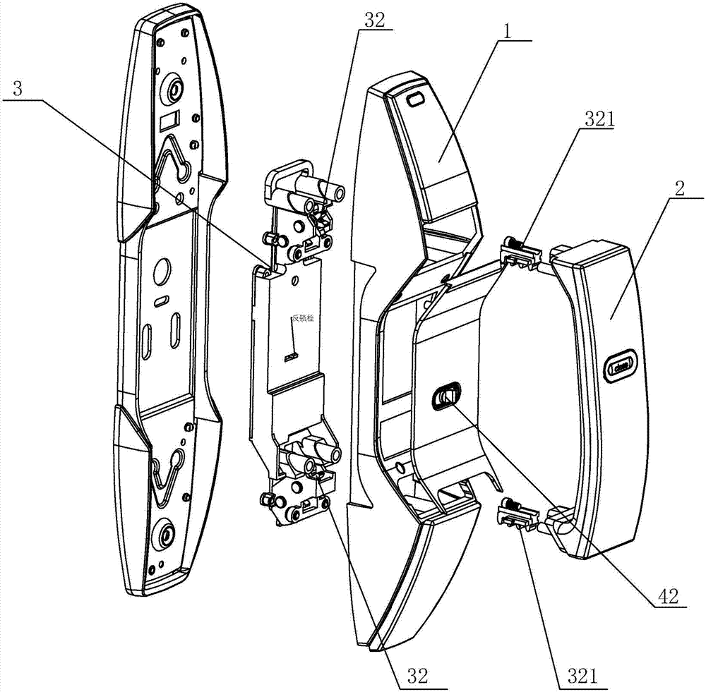
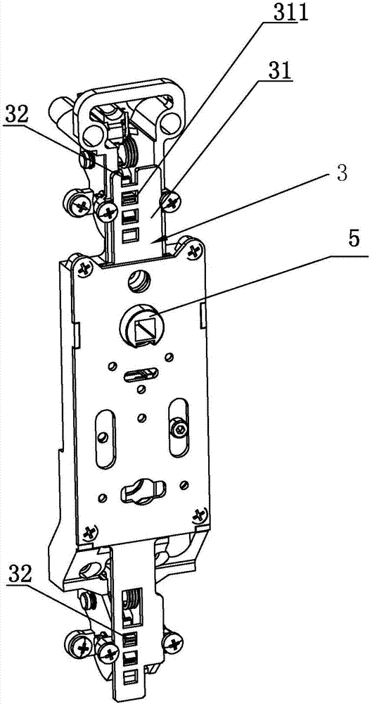
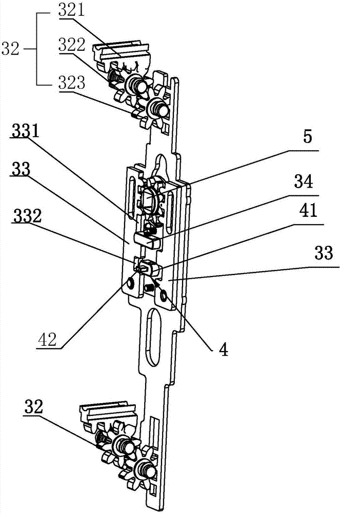
[0012] Refer to attached Figure 1 to Figure 3 An embodiment of a push-pull lock of the present invention is further described in detail.

[0013] A push-pull lock, including a lock case 1 and a push-pull handle 2 provided on the lock case 1, a push-pull mechanism 3 and an anti-lock mechanism 4 for locking the push-pull mechanism 3 are arranged in the lock case 1, and the push-pull mechanism 3 includes a push-pull slide plate 31; both ends of the push-pull sliding plate 31 are provided with a push-pull gear assembly 32, the push-pull gear assembly 32 includes a push-pull rack 321, a driving gear 322 and a driven gear 323, one end of the push-pull rack 321 is connected to the push-pull The handle 2 is connected, and the other end is meshed with the driving gear 322, and the driving gear 322 is meshed with the driven gear 323; wherein the two ends of the push-pull sliding plate 31 are respectively provided with several evenly spaced tooth holes 311, so The toothed hole 311 is m...


PUM


Abstract

The invention discloses a push and pull lock. The lock comprises a lock shell and a push and pull handle arranged on the lock shell. a push and pull mechanism and a double lock mechanism used for locking the push and pull mechanism are arranged in the lock shell, the push and pull mechanism comprises a push and pull sliding plate, two ends of the push and pull sliding plate are each provided witha push and pull gear assembly, one end of a push and pull rack is connected with the push and pull handle, the other end of the push and pull rack is engaged with a driving gear, the driving gear is engaged with a driven gear, the two ends of the push and pull sliding plate are each provided with multiple evenly-distributed gear holes in a spaced manner, the gear holes are matched with the drivengear, two rotating racks which are arranged in a spaced manner are arranged on the push and pull sliding plate, a square rod rotating shaft is arranged between the two transmission racks, and is engaged with the transmission racks, when the push and pull handle moves front and back, the square rod rotating shaft can be driven to rotate, a spring bolt driven to stretch out and draw back, unlockingor locking can be achieved, the structure is simple, and meanwhile, the lock can be suitable for arranging manners of different positions of doors and door frames.

Description

technical field [0001] The invention relates to the field of locks, more specifically, it relates to a push-pull lock. Background technique [0002] The push-pull mechanism of the push-pull lock is used to transmit the power of the user to the shaft of the square rod, and the shaft of the square rod drives the bolt to expand and contract, so as to realize the unlocking action of the push-pull lock. When the structure of the existing push-pull lock is complex, the manufacturing cost is increased, and the general The push-pull mechanism of the push-pull lock can only meet one of the unlocking methods of "left push" or "left pull" or "right push" or "right pull". Therefore, it is necessary to know the positional relationship between the door and the door frame before installation, and according to The preset way of opening the door is to select the corresponding push-pull lock; however, in the actual operation process, due to human misjudgment, the push-pull lock cannot meet th...

Claims


Application Information

Patent Timeline
Patent Type & Authority Applications(China)
IPC IPC(8): E05B63/04E05B13/00
CPCE05B13/002E05B63/04Y02T10/7072
Inventor 许平稳
Owner WENZHOU JUSHI SECURITY TECH CO LTD
Why Eureka
Try Eureka