
LED (Light-Emitting Diode) backlight driving circuit and liquid crystal display

A technology of backlight drive circuit and booster circuit, which is applied in the direction of static indicators, lamp circuit layout, light source, etc., can solve the problem of flickering of the drive circuit, and achieve the effect of avoiding flickering

Active Publication Date: 2014-04-23
TCL CHINA STAR OPTOELECTRONICS TECH CO LTD
View PDF7 Cites 14 Cited by
  • Summary
  • Abstract
  • Description
  • Claims
  • Application Information

AI Technical Summary

Problems solved by technology

In this kind of circuit, when the time interval of restarting is very short, the charge stored in the booster circuit 110 has not been completely released, and the driving circuit will still flicker when restarting.

Method used


Image

  • LED (Light-Emitting Diode) backlight driving circuit and liquid crystal display
  • LED (Light-Emitting Diode) backlight driving circuit and liquid crystal display
  • LED (Light-Emitting Diode) backlight driving circuit and liquid crystal display

Examples


Embodiment Construction

[0025] The present invention will be further described below with embodiments in conjunction with the accompanying drawings.

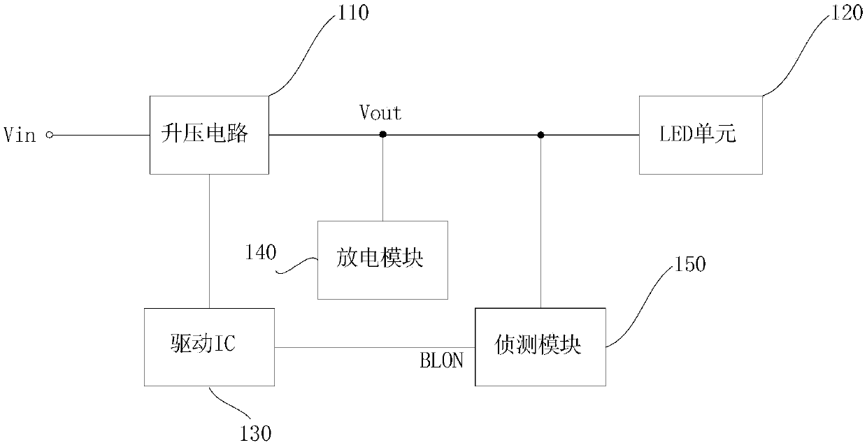
[0026] figure 2 It is a connection block diagram of the LED backlight driving circuit in a specific embodiment of the present invention.

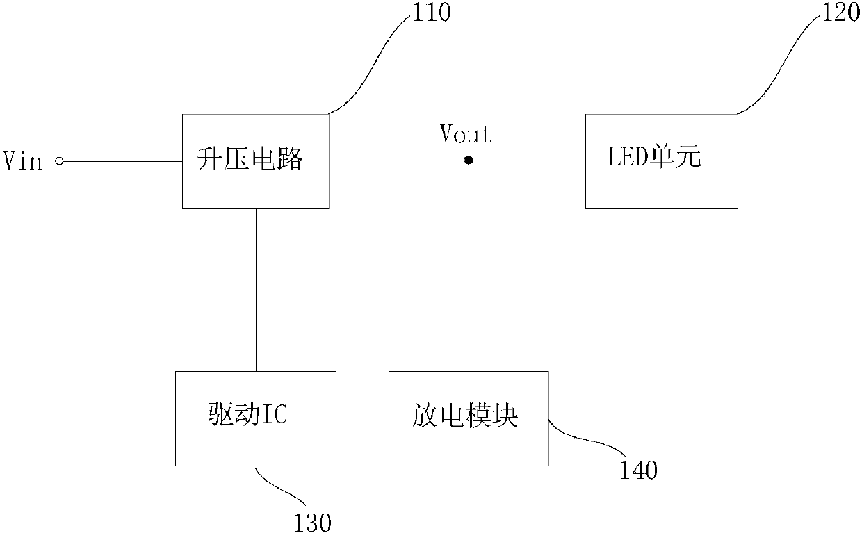
[0027] refer to figure 2 , the LED backlight driving circuit in this embodiment includes a boost circuit 110, which is used to convert the input voltage Vin into the required output voltage Vout and provide it to the LED unit 120; the driving IC 130 controls the boost circuit 110, so that the boost The voltage circuit 110 converts the input voltage into a required output voltage and provides it to the LED unit 120; the discharge module 140 is used to release the charge stored in the boost circuit 110 after the drive circuit is turned off; the detection module 150 is used to detect the boost Voltage at the output terminal of voltage circuit 110 and generate an enabling signal, the enabling signal is connected to ...


PUM


Abstract

The invention discloses an LED (Light-Emitting Diode) backlight driving circuit, which comprises a step-up circuit, a driving IC (Integrated Circuit), a discharge module and a detection module, wherein the step-up circuit is used for converting input voltage into required output voltage and supplying the output voltage to an LED unit; the driving IC is used for controlling the step-up circuit to enable the step-up circuit to convert the input circuit into the required output voltage and supply the output voltage to the LED unit; the discharge module is used for releasing charges stored in the step-up circuit after the driving circuit is turned off; the detection module is used for detecting the voltage at the output end of the step-up circuit and generating an enable signal which is used for controlling the working state of the driving IC. In the LED backlight driving circuit provided by the invention, when the driving circuit is turned off and then is quickly turned on again, the detection module can detect the discharge situation of the step-up circuit and the driving circuit is turned on only when the charges stored in the step-up circuit are released and the output voltage is enabled to be smaller than reference voltage, so that the phenomenon of flashing is fully avoided. The invention additionally provides a liquid crystal display with the LED backlight driving circuit.

Description

technical field [0001] The invention relates to an LED backlight driving circuit, in particular to an LED backlight driving circuit capable of avoiding flickering when restarting quickly after being turned off, and a liquid crystal display provided with the LED backlight driving circuit. Background technique [0002] With the continuous advancement of technology, the backlight technology of liquid crystal display devices has been continuously developed. Traditional liquid crystal display devices use cold cathode fluorescent lamps (CCFL) as backlight sources. However, due to the shortcomings of CCFL backlight such as poor color reproduction ability, low luminous efficiency, high discharge voltage, poor discharge characteristics at low temperature, and long time for heating to reach a stable gray level, the backlight technology using LED backlight has been developed; In the liquid crystal display device, the LED backlight is arranged opposite to the liquid crystal display pan...

Claims


Application Information

Patent Timeline
IPC IPC(8): H05B37/02G09G3/34
CPCH05B45/38
Inventor 张先明
Owner TCL CHINA STAR OPTOELECTRONICS TECH CO LTD
Features
  • Generate Ideas
  • Intellectual Property
  • Life Sciences
  • Materials
  • Tech Scout
  • Unparalleled Data Quality
  • Higher Quality Content
  • 60% Fewer Hallucinations
Learn More