
Cages for Radial Roller Bearings

A roller bearing and cage technology, which is applied in the field of radial roller bearing cages, can solve the problems of unrestricted relative displacement and stable holding of rollers.

Inactive Publication Date: 2016-11-23
NSK LTD
View PDF6 Cites 0 Cited by
  • Summary
  • Abstract
  • Description
  • Claims
  • Application Information

AI Technical Summary

Problems solved by technology

However, although the relative displacement of one end and the other end of the cage 7b in the axial direction is limited by the mutual engagement of the first concave-convex portion 15a and the second concave-convex portion 16a, the relative displacement of the two in the circumferential direction is not restricted. displacement
Therefore, when the retainer 7b elastically deforms and expands in diameter, there is a possibility that a pocket on the side of the engaging portion may appear due to a change in the state of engagement between the first engaging concave portion 18a and the second engaging convex portion 19a. If the width of 23 in the circumferential direction increases, the roller cannot be held stably in the pocket 23 on the side of the engaging part.

Method used


Image

  • Cages for Radial Roller Bearings
  • Cages for Radial Roller Bearings
  • Cages for Radial Roller Bearings

Examples


Embodiment Construction

[0078] Embodiment 1

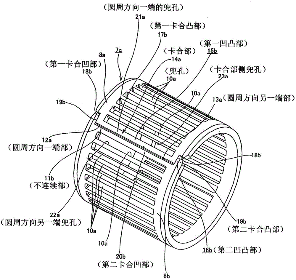
[0079] figure 1 It is a schematic diagram of the first example of the embodiment of the present invention. In addition, the present invention is characterized in that the cage 7c for a radial roller bearing has a discontinuous portion 11b in at least a part of the circumferential direction, and the end portions (one end portion 12a in the circumferential direction, one end portion 12a in the circumferential direction, and The other end portions 13a) are engaged with each other by the engaging portion 14a, and the structure of the engaging portion 14a is improved. Other structures include Figure 6-9 The existing structure shown is roughly the same as the conventionally known structure of the radial roller bearing cage, therefore, the description of the same components as the existing structure is omitted or simplified, and the characteristic parts of this example are as follows: Center is explained.

[0080] The radial roller bearing cage 7c of this ...


PUM


Abstract

The present invention relates to a cage for a radial roller bearing, which can prevent the pocket (21a) at one end of the circumferential direction and the pocket (21a) at the other end of the circumferential direction ( 22a) The structure in which the surface pressure of the rolling contact portion between the rolling surface of each roller and each raceway of the outer ring and inner ring is too large. It consists of a first concave-convex portion (15b) and a second concave-convex portion (16b) in the axial direction between one end portion (12a) in the circumferential direction (12a) and the other end portion (13a) in the circumferential direction that prevent the discontinuous portion (11b) from being arranged. The engaging part (14a) that engages in the state of relative displacement. And the first concavo-convex portion (15b) is composed of a first engaging convex portion (17b) and a pair of first engaging concave portions (18b, 18b). And the second concavo-convex portion (16b) is composed of a pair of second engaging convex portions (19b, 19b) and a second engaging concave portion (20b). In addition, an engaging part side pocket (23a) is formed in the first engaging convex part (17b) in a state of penetrating the first engaging convex part (17b) in the radial direction.

Description

technical field [0001] The invention relates to an improvement of a cage for radial roller (including needle roller) bearings. More specifically, it relates to a cage for a radial roller bearing having a discontinuous portion at least one location in the circumferential direction, and end portions provided across the discontinuous portion are engaged with each other at engaging portions. By improving the structure of the above-mentioned engaging portion, it is possible to prevent the rolling surface of each roller arranged between the pocket at one end in the circumferential direction and the pocket at the other end in the circumferential direction sandwiching the above-mentioned discontinuous portion from contacting the outer ring and the inner ring. The surface pressure of the rolling contact part between the raceways of the ring is too large. Background technique [0002] The part to which a large radial load is applied in the rotating support part of various mechanical ...

Claims


Application Information

Patent Timeline
Patent Type & Authority Patents(China)
IPC IPC(8): F16C33/51
CPCF16C19/463F16C19/48F16C33/4635F16C33/4694F16C2300/02F16C33/467
Inventor 石桥丰
Owner NSK LTD
Learn More