A Pneumatic Pressurized Ladle Sliding Nozzle Mechanism

A sliding nozzle and steel ladle technology, which is applied in metal processing equipment, casting molten material containers, casting equipment, etc., can solve the problems that the popularization and application of pneumatic pressurization mechanism cannot promote the application of steel ladles in large quantities, so as to reduce the consumption of spare parts and eliminate human factors Influencing and reducing the effect of slide plate breakout production accidents

Active Publication Date: 2017-08-01
HENAN RONGJIN HIGH TEMPERATRUE MATERIALS CO LTD
View PDF5 Cites 0 Cited by
  • Summary
  • Abstract
  • Description
  • Claims
  • Application Information

AI Technical Summary

Problems solved by technology

[0005] In order to achieve the above object, the technical solution of the present invention is: a pneumatic pressurized ladle sliding nozzle mechanism, including a fixed frame, an opening and closing frame, a sliding frame, an upper nozzle, a lower nozzle, a lower nozzle seat, a lower nozzle tensioner, an upper Sliding plate, sliding plate, surface pressure bolts and driving device, surface pressure limiting platforms are symmetrically arranged on both sides of the fixed frame, surface pressure limiting platforms are equipped with surface pressure locking nuts, spring chambers are symmetrically arranged on both sides of the opening and closing frame, A spring pressing plate is arranged in the spring chamber, and surface pressure support columns are arranged at intervals under the spring pressure plate. A number of spring guide columns are arranged on the inner and outer sides of the adjacent two surface pressure support columns, and spring guide columns are provided with springs; Sliding rails are arranged on the side, and fixed sliding rails matching the sliding rails are arranged on both sides of the opening and closing frame; an upper sliding plate is arranged in the brick cavity of the fixed frame, and the upper nozzle is set in the fixed frame and contacts the upper sliding plate, and the bricks of the sliding frame There is a sliding plate in the cavity, and the drain is set in the drain seat and tightened with the drain clamp; the driving device is set on the top of the fixed frame and connected with the sliding frame; by setting the surface pressure support column and the surface pressure limit platform, Eliminate the influence of surface pressure bolts and spring pressure plates on the surface pressure of the mechanism due to rotational wear during the pressurization process, ensure uniform and stable surface pressure of the mechanism and eliminate the influence of human factors, and increase the service life of surface pressure bolts and spring pressure plates by more than 4 times , the total height of the mechanism is reduced by about 30-60mm, which solves the difficulty in popularizing and applying the pneumatic pressurizing mechanism on small and medium ladles, especially the technical problem that the 150mm stroke pneumatic pressurizing mechanism cannot be popularized and applied in a large number of steel ladles below 90 tons

Method used


Image

  • A Pneumatic Pressurized Ladle Sliding Nozzle Mechanism
  • A Pneumatic Pressurized Ladle Sliding Nozzle Mechanism
  • A Pneumatic Pressurized Ladle Sliding Nozzle Mechanism

Examples


Embodiment Construction

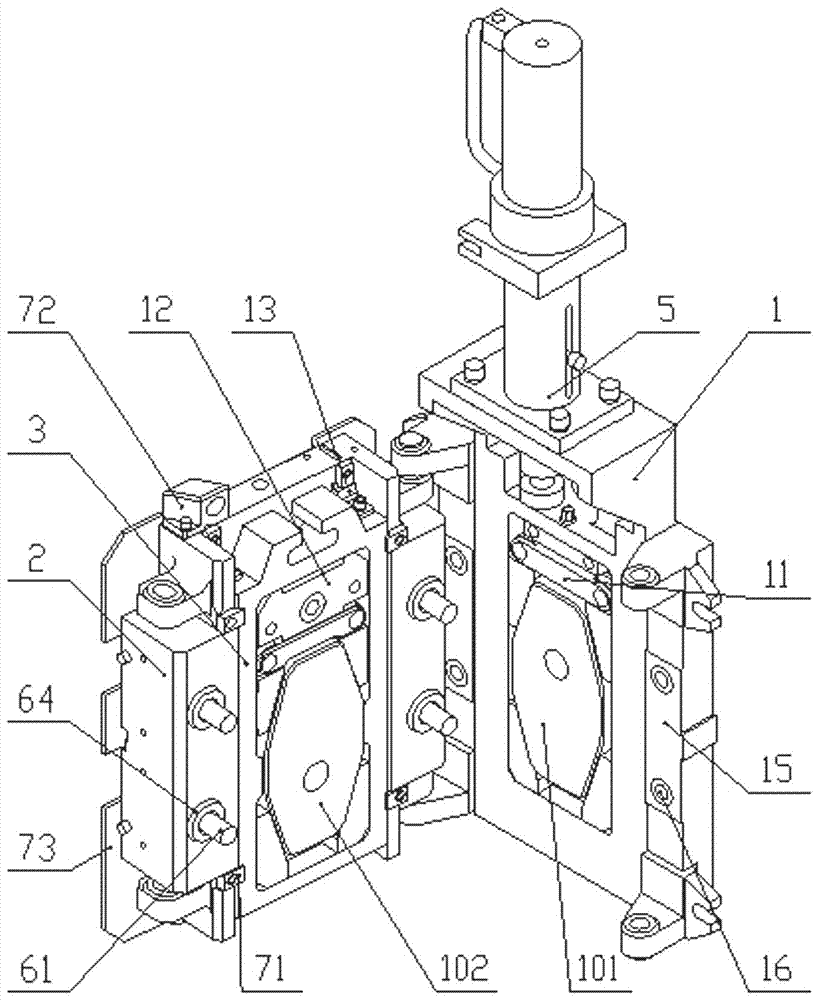
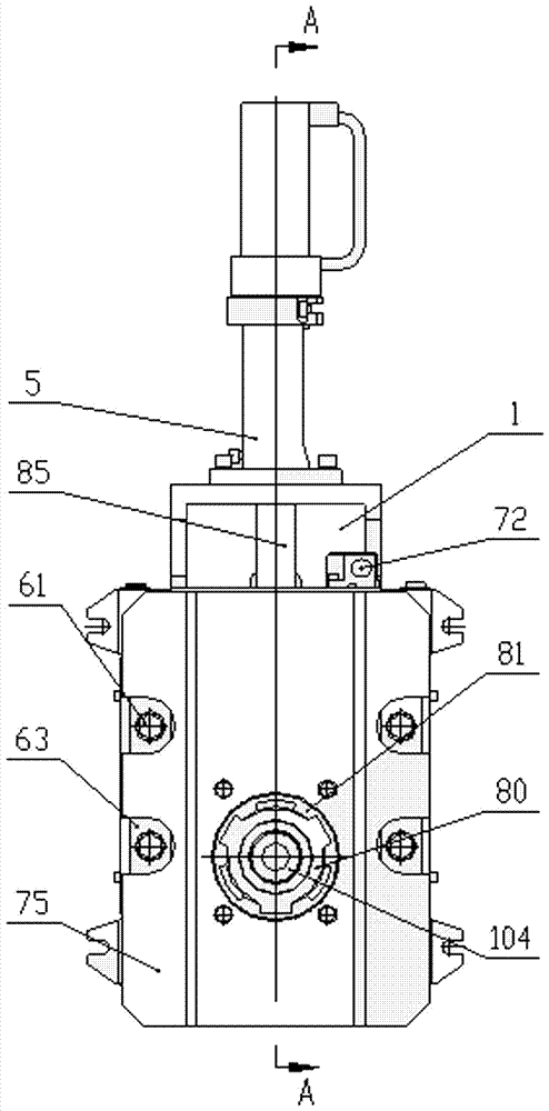
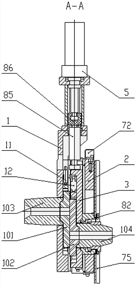
[0022] See attached Figure 1-9 , a pneumatic pressurized ladle sliding nozzle mechanism, including a fixed frame 1, an opening and closing frame 2, a sliding frame 3, a lower nozzle seat 81, a lower nozzle tensioner 80, an upper sliding plate 101, a lower sliding plate 102, an upper nozzle 103, a lower Nozzle 104, surface pressure bolts 61, driving device 5, surface pressure lock nuts 16 and surface pressure limiters 15 are symmetrically arranged on both sides of the fixed frame 1, spring chambers 60 are symmetrically arranged on both sides of the opening and closing frame 2, spring chambers 60 Spring pressing plate 63 is arranged inside, and surface pressure supporting column 64 is arranged at intervals below spring pressing plate 63, and several spring guiding columns 67 are arranged on the inner and outer sides of adjacent two sides pressing supporting column 64, and spring guiding column 67 is provided with spring 62; and the spring pressing plate 63 are all provided with...


PUM


Abstract

The invention discloses a pneumatic pressurized ladle sliding nozzle mechanism. The pneumatic pressurized ladle sliding nozzle mechanism comprises a fixed framework, an opening and closing framework, a sliding framework, a lower nozzle base, a lower nozzle ejector, an upper sliding plate, a lower sliding plate, an upper nozzle, a lower nozzle, a surface compression bolt, a sliding plate compression device and a driving device. When the pneumatic pressurized ladle sliding nozzle mechanism performs pressurization, the surface compression bolt penetrates a spring pressing plate, a surface compression supporting column and a round hole in the bottom of a spring chamber, and is tightly screwed into a surface compression locking nut so that the fixed framework and the opening and closing framework can be connected together and compress the sliding framework; a spring in the spring chamber is compressed, pressure of the spring is evenly transmitted to the sliding framework through a fixed sliding rail, and the driving device drives the sliding framework to do reciprocating motion to drive the upper sliding plate and the lower sliding plate to slide smoothly to realize steel pouring. The pneumatic pressurized ladle sliding nozzle mechanism is easy to operate and convenient to maintain, surface pressure of the mechanism is generated stably, the spring pressure is transmitted evenly, the continuous sliding rate of the sliding plates is high, part consumption is low, the composite cost is high, the safety performance is good, and the mechanism is small in total height and suitable for being applied and popularized to small and medium sized ladles.

Description

technical field [0001] The invention relates to a pneumatic pressurized ladle sliding nozzle mechanism, which is used to realize the flow control and pouring process of ladle molten steel, belonging to steelmaking machinery, in particular to a pneumatic pressurized ladle sliding nozzle installed outside the bottom of the ladle mechanism. Background technique [0002] In the currently known pneumatic pressurization and pneumatic pressurization ladle sliding nozzle mechanism, it is a left and right door-opening structure. ) and are connected with threads. During the pressurization operation, the face pressure bolt is tightened with a pneumatic tool, and the head of the face pressure bolt is rotated while pressing against the spring pressure plate to complete the pressurization operation of the ladle mechanism. [0003] This form of pneumatic pressurized ladle mechanism has the following disadvantages: ①During the pneumatic pressurization operation, the maximum force on a sing...

Claims


Application Information

Patent Timeline
Patent Type & Authority Patents(China)
IPC IPC(8): B22D41/24
Inventor 万立新徐跃庆李宏宇梁保青张江伟王长伟
Owner HENAN RONGJIN HIGH TEMPERATRUE MATERIALS CO LTD
Why Eureka
Try Eureka