Stamped sealing arrangement for flat flanged joint

A sealing device, flat flange technology, applied in the direction of engine sealing, engine components, mechanical equipment, etc., to achieve the effect of small insertion height, material saving, and leakage rate improvement

Inactive Publication Date: 2003-04-23
阿尔弗雷德·容
View PDF5 Cites 0 Cited by
  • Summary
  • Abstract
  • Description
  • Claims
  • Application Information

AI Technical Summary

Problems solved by technology

A big disadvantage of this solution is that the applied bolt pressure is not applied as desired to a narrow sealing area, but to the entire sealing area of ​​the seal

Method used


Image

  • Stamped sealing arrangement for flat flanged joint
  • Stamped sealing arrangement for flat flanged joint
  • Stamped sealing arrangement for flat flanged joint

Examples


Embodiment Construction

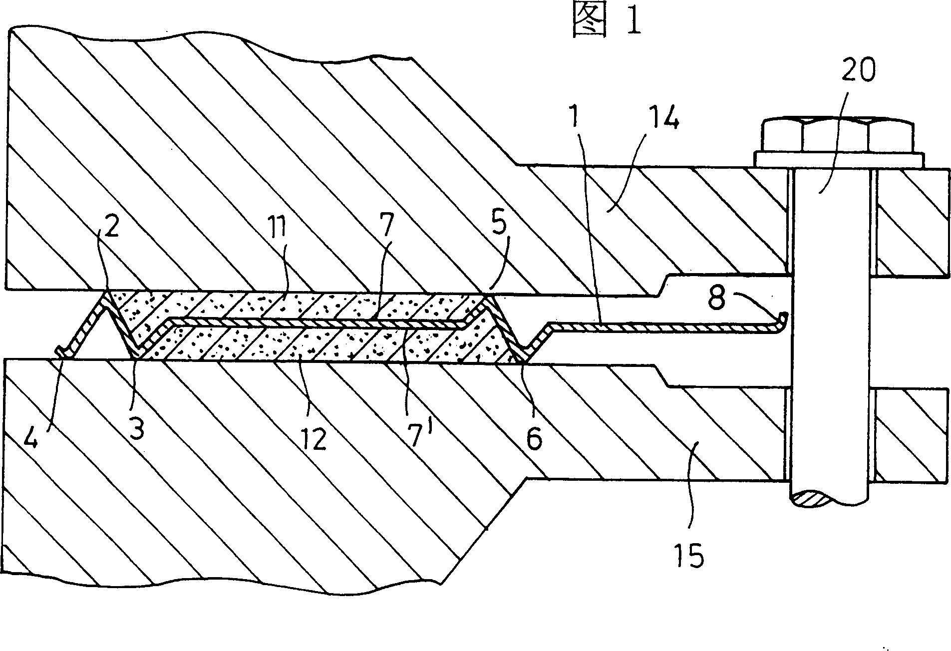
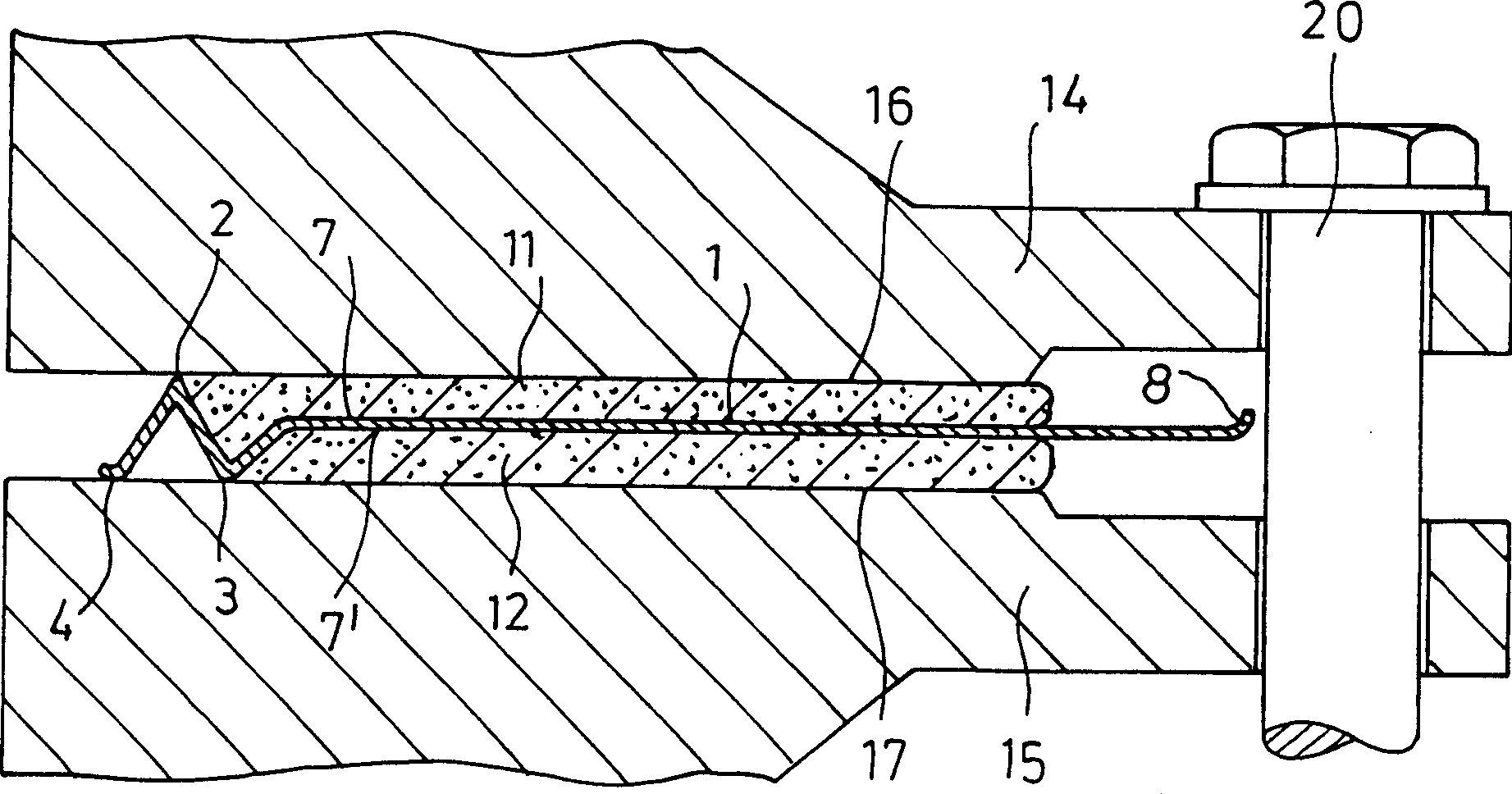
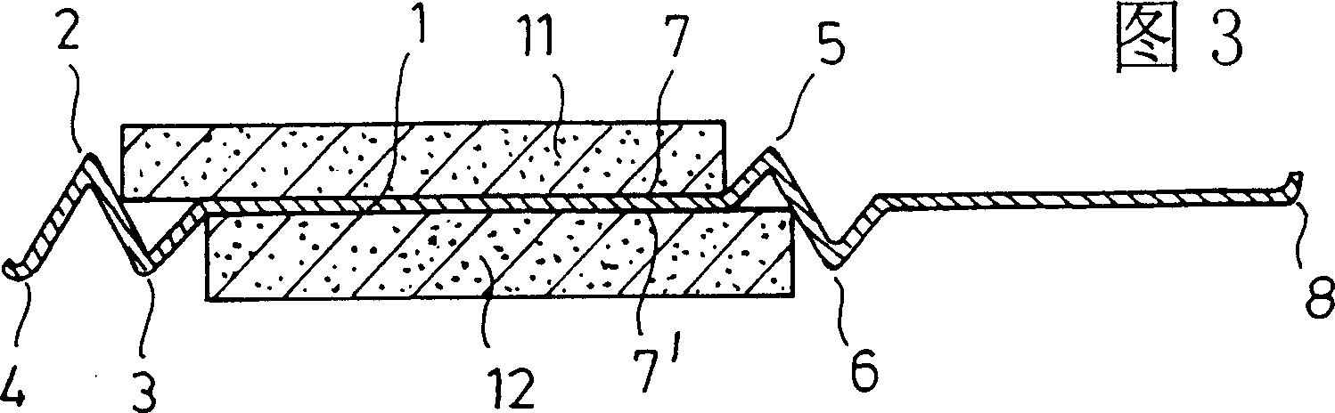
[0030] In these figures, the symbols have the following meanings:

[0031] 1 Part of the matrix

[0032] 2, 3, 4, 5, 6 and 9 ring teeth

[0033] 7, 7’ Load bearing surface for soft material supports

[0034] 8 Beading on outer edge of centering ring

[0035] 11, 12 Soft material supports

[0036] 14, 15 Flange part

[0037] 20 bolt local

[0038] In these figures it is assumed that the seal has been installed horizontally. Therefore, reference is made to the right or left part of the seal. Of course, the seal can be mounted in any desired orientation. If they were mounted vertically, then the upper and lower parts would have to be referenced. Due to the rotational symmetry of the seal, only the cross-section of the right part is always shown in the figures.

[0039] FIG. 1 shows the seal on an enlarged scale in a mounted state between flanges 14 and 15 . It consists of a base body 1 and two soft material supports 11 and 12 . The base body is preferably metallic, whi...


PUM


Abstract

The invention relates to a sealing arrangement for a flat flanged joint, comprising a preferably metal base body (1). Said base body has bearing surfaces (7, 7') on each of its two sides for ring-shaped supports made of a soft material (11,12). The bearing surfaces (7, 7') are flat over a large area and are situated essentially directly opposite each other. At least one ring tooth (2, 3) is provided in the inner radial area of each bearing surface and at least one ring tooth (5, 6) is also preferably provided in the outer radial area of each bearing surface. The soft material supports are each fixed on the bearing surfaces (7, 7'). When the arrangement is assembled, the ring teeth (2, 3, 4, 5, 6) come to rest on the flange surfaces (14, 15) and the soft material supports (11, 12) are at least inwardly limited by the ring teeth (2, 3). The wall of the base body (1) is only 0.2 to 2.0 mm, preferably 0.3 to 1.2 mm thick and the ring teeth are configured by stamping in such a way that the entire wall extends angularly or in a wave shape, enabling points of metallic contact with the flange surfaces (14, 15).

Description

technical field [0001] The invention relates to a sealing device for flat flange joints, comprising a preferably metallic base body having on each of its two sides a bearing for an annular support made of soft material surfaces, the bearing surfaces being flat over most areas and positioned substantially directly opposite each bearing surface, at least one ring tooth is provided in the inner radial region of each bearing surface, and preferably also on the outside of each bearing surface At least one ring tooth is provided in the radial region, the soft material support is respectively fixed on the bearing surface, when the device is assembled, the ring tooth rests on the flange surface, and the soft material support is at least limited inwardly by the ring tooth . Background technique [0002] A common sealing device is known from DE29504402U1. The two bearing surfaces are planar over most areas and are located substantially directly opposite each other. In the outer rad...

Claims


Application Information

Patent Timeline
Patent Type & Authority Patents(China)
IPC IPC(8): F16J15/12
CPCF16J15/127
Inventor 阿尔弗雷德·容
Owner 阿尔弗雷德·容
Why Eureka
Try Eureka