
Slotted cam conveying mechanism

A technology of conveying mechanism and groove cam, which is applied in the direction of conveyor, transportation and packaging, can solve the problem that the spring cannot achieve stable and continuous work, and achieve the effect of stable work.

Inactive Publication Date: 2014-04-30
CHONGQING MING SHIELD ELECTROMAGNETIC VALVE
View PDF0 Cites 0 Cited by
  • Summary
  • Abstract
  • Description
  • Claims
  • Application Information

AI Technical Summary

Problems solved by technology

[0004] The invention provides a slotted cam conveying mechanism to solve the problem that using a spring as a restoring force cannot achieve stable and continuous work

Method used


Image

  • Slotted cam conveying mechanism

Examples


Embodiment Construction

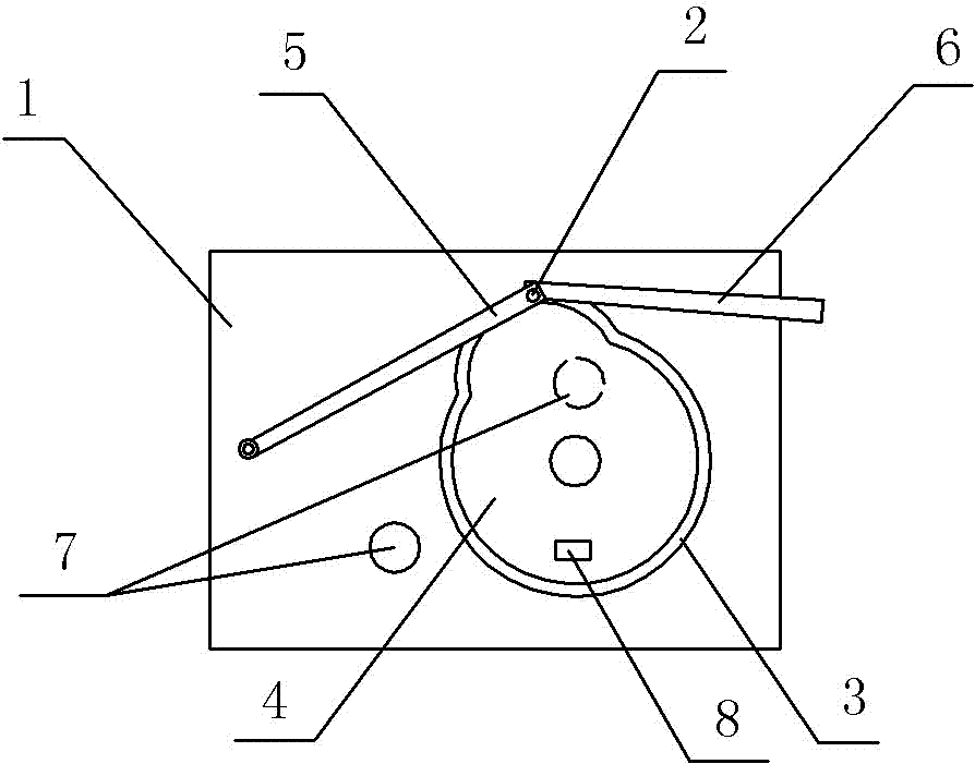
[0011] like figure 1 As shown, a conveying mechanism with a grooved cam 4 in this embodiment includes a base 1, a follower 2, a cam 4 with a guide groove 3, a connecting rod 5 and a push rod 6, and one end of the connecting rod 5 is connected to On the base 1, the other end is connected with the push rod 6, one end of the follower 2 is arranged on the end of the connecting rod 5 close to the push rod 6, and the other end is slidably connected in the guide groove 3 of the cam 4, the base 1 is provided with a plurality of cam mounting holes 7, and a temperature sensor 8 is provided on the cam.

[0012] One end of the connecting rod 5 is connected to the base 1, and the follower 2 on the connecting rod 5 moves along the guide groove 3 of the cam 4 to realize the rotation of the connecting rod 5. Because the push rod 6 is connected with the connecting rod 5, the pushing The rod 6 can swing back and forth within a certain range and can be used to push materials. The base is provi...


PUM


Abstract

The invention discloses a slotted cam conveying mechanism. The slotted cam conveying mechanism comprises a substrate, a driven rotor, a cam provided with a guide slot, a connecting rod and a push rod, wherein one end of the connecting rod is connected onto the substrate, and the other end of the connecting rod is connected with the push rod; one end of the driven rotor is arranged on the connecting rod, and the other end of the driven rotor is connected into the guide slot of the cam in a sliding manner. The slotted cam conveying mechanism can realize reciprocating motion in other directions except the gravity direction; meanwhile the structure is rod-shaped structure, a spring is not used, the work is relatively stable, and longer continuous work can be realized.

Description

technical field [0001] The present invention belongs to the technical field of conveying devices. Background technique [0002] A cam can be defined as a component with a curved surface or a curved groove. By using its swing or rotation, another component - the follower can provide a preset motion. In its return stroke, it sometimes relies on its own weight, but some mechanisms often use springs as the return force in order to obtain exact movements. [0003] However, relying on its own weight, it can only achieve reciprocating motion in the direction of gravity; if a spring is used as the restoring force, the life of the spring is short, and stable and continuous work cannot be achieved. Contents of the invention [0004] The invention provides a cam conveying mechanism with grooves to solve the problem that using a spring as a restoring force cannot realize stable and continuous work. [0005] In order to solve the above-mentioned technical problems, the present invent...

Claims


Application Information

Patent Timeline
Patent Type & Authority Applications(China)
IPC IPC(8): B65G25/08
Inventor 姜静慧
Owner CHONGQING MING SHIELD ELECTROMAGNETIC VALVE
Learn More