Workpiece orientation device with push rod

A technology of orienting device and push rod, which is applied in the direction of conveyor objects, transportation and packaging, etc., and can solve problems such as inability to realize workpieces

Inactive Publication Date: 2014-04-30
CHONGQING MING SHIELD ELECTROMAGNETIC VALVE
View PDF0 Cites 5 Cited by
  • Summary
  • Abstract
  • Description
  • Claims
  • Application Information

AI Technical Summary

Problems solved by technology

[0003] The technical problem to be solved by the present invention is that in the prior art, the directional transmission of wo

Method used


Image

  • Workpiece orientation device with push rod

Examples


Embodiment Construction

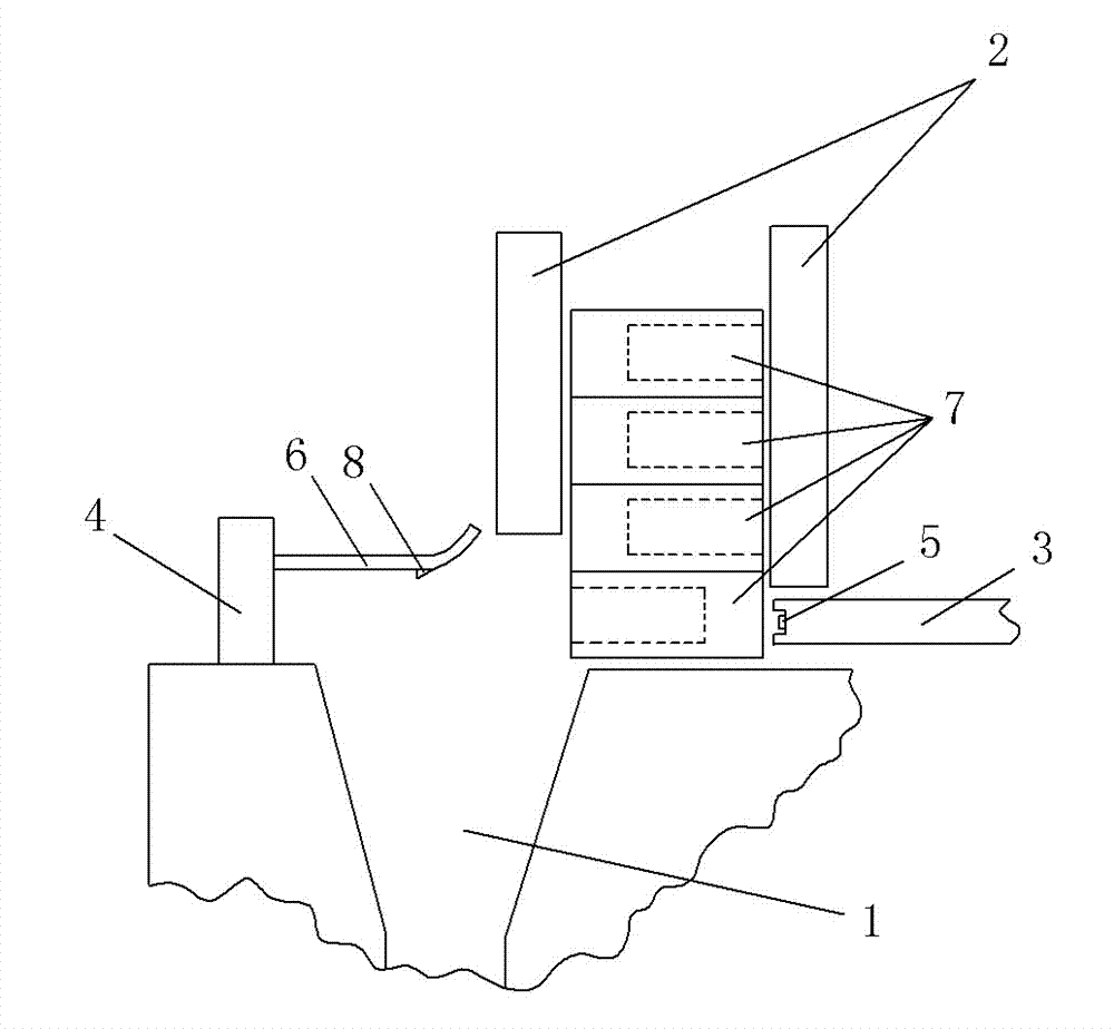
[0009] The reference signs in the accompanying drawings of the specification include: a positioning groove 1 , a feeding chute 2 , a push rod 3 , a baffle 4 , an infrared probe 5 , an elastic pressure plate 6 , a workpiece 7 , and a blocking piece 8 .

[0010] Below in conjunction with accompanying drawing and embodiment the technical solution of the present invention is further described:

[0011] Such as figure 1 As shown, a workpiece orientation device with a push rod includes a frame, a positioning groove 1 arranged on the frame, a feeding chute 2, a push rod 3 and a baffle 4, the push rod 3 is connected with a driving device, and the drive The device is preferably a propulsion cylinder, the feeding chute 2 is arranged on one side of the positioning groove 1, the bottom of the feeding chute 2 is provided with a reciprocating push rod 3, and the other side of the positioning groove 1 opposite to the push rod 3 is provided with a stopper. The plate 4 and the end of the push...


PUM


Abstract

The invention discloses a transportation device, and particularly relates to a workpiece orientation device with a push rod. The workpiece orientation device comprises a frame, a positioning groove, feeding chutes, the push rod and a baffle, the positioning groove is formed in the frame, the push rod is connected with a driving device, the feeding chutes are formed in one side of the positioning groove, the reciprocating push rod is arranged at the bottoms of the feeding chutes, the baffle is arranged on the other side of the positioning groove opposite to the push rod, a groove is formed in the end of the push rod, and an infrared probe is arranged in the groove. By the aid of the technical scheme, an orientation transmission mechanism is simple in structure, and workpieces can be transmitted in an oriented manner.

Description

technical field [0001] The invention relates to a transportation device, in particular to a workpiece orientation transmission mechanism. Background technique [0002] In the machinery manufacturing industry, a large number of parts need to be processed and transported. A workpiece with a hole on one end is a very common part to be processed in mechanical processing. The asymmetric shape of the two ends of the workpiece requires it to be placed neatly when it is to be processed. However, at present, it is placed manually The open method not only leads to inefficiency, but also increases labor costs. Contents of the invention [0003] The technical problem to be solved by the present invention is that in the prior art, the directional transmission of workpieces with holes on one end surface cannot be realized, manual placement is required, and the transmission efficiency is low. [0004] In order to solve the above technical problems, a workpiece orientation device with a...

Claims


Application Information

Patent Timeline
IPC IPC(8): B65G47/74B65G47/82
Inventor 姜静慧
Owner CHONGQING MING SHIELD ELECTROMAGNETIC VALVE
Why Eureka
Try Eureka