
Short fiber jet orientation forming process

A molding process and short fiber technology, which is applied in the field of short fiber spray orientation molding technology, can solve the problems of high input cost, low production efficiency, inconsistent flow speed, etc., achieve cost advantages, improve production efficiency, and facilitate mass production Effect

Active Publication Date: 2021-06-25
SHENZHEN HFC SHIELDING PRODS CO LTD
View PDF7 Cites 0 Cited by
  • Summary
  • Abstract
  • Description
  • Claims
  • Application Information

AI Technical Summary

Problems solved by technology

[0003] At present, there are two main methods of carbon fiber orientation sorting. The first one is to sort carbon fibers by using a strong magnetic field, but this sorting method requires a magnetic field strength of more than 5T. This strong magnetic field not only requires the purchase of expensive equipment, but also has low production efficiency. Achieving large-scale production will also have adverse effects on the surrounding environment; and the second sorting method is to use an ordinary screw extruder. This sorting method mainly uses the shear force of the screw to achieve directional sorting of carbon fibers, but this kind of sorting There are great requirements on the viscosity and hardness of the preparatory material. In addition, the flow velocity of the preparatory material containing carbon fiber in the extrusion flow channel is inconsistent, resulting in incomplete orientation of the carbon fiber, resulting in poor thermal conductivity stability of the product.
[0004] In view of the related technologies mentioned above, the inventor believes that according to the current production method, the requirements for equipment are relatively high, the input cost is large, and the process is relatively cumbersome.

Method used


Image

  • Short fiber jet orientation forming process
  • Short fiber jet orientation forming process
  • Short fiber jet orientation forming process

Examples


Embodiment Construction

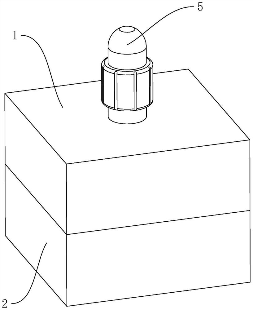
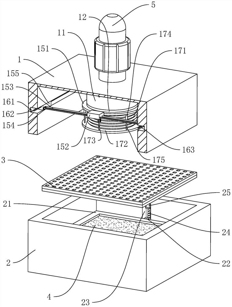
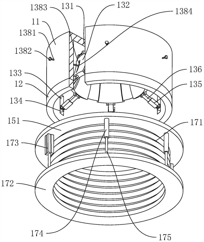
[0043] The following is attached Figure 1-6 The application is described in further detail.

[0044] The embodiment of the present application discloses a forming process of short fiber spray orientation.

[0045] refer to figure 2 , including: S1: Preparation of semi-crosslinked carrier 4.

[0046] S2: installing the semi-crosslinked carrier 4 , installing the semi-crosslinked carrier 4 on the installation frame 21 .

[0047] S3: Start the short fiber spray orientation device, spray the short fiber to the semi-crosslinked carrier 4 for orientation and shaping, and form a product surface with an area of ​​150*150mm.

[0048] S31: Install short fibers on equipment with spraying function. The loading barrel has a blast function, which can preliminarily disperse short fibers and prevent agglomeration. There are more than two layers of filter screens in the spraying device, which can further restrain short fibers The injection state ensures that the length of the short fiber...


PUM


Abstract

The invention relates to a short fiber jet orientation forming process, and belongs to the technical field of short fiber forming processes. The short fiber jet orientation forming process comprises the following steps of S1, preparing a semi-crosslinking carrier; S2, installing the semi-crosslinking carrier; S3, starting a short fiber jet orientation device, jetting short fibers to the semi-crosslinking carrier for directional shaping, and forming a product surface with the area of 150 * 150 mm; and S4, carrying out deep curing on the semi-crosslinked carrier loaded with the short fibers for 20 min. In order to realize uniform and ordered orientation of short carbon fibers under the condition that the cost is not increased, the invention provides the short fiber jet orientation forming process which can improve the forming quality of short fiber products.

Description

technical field [0001] The present application relates to the technical field of short fiber forming process, in particular to a forming process of short fiber spray orientation. Background technique [0002] With the rapid development of the network, various electronic products are developing in the direction of miniaturization, refinement and high power, and the integration density of transistors has greatly increased. The substantial increase in electronic integration means that the electronic components packaged in the circuit board will generate more heat. If the heat is not conducted in time, it will cause rapid accumulation of heat in electronic products, which will increase the operating temperature of electronic components. High, affecting the normal operation of the equipment. The conventional operation is to use thermal pads to quickly transfer heat from the heat source to the heat sink, and thermal pads usually use high filling to improve thermal conductivity. ...

Claims


Application Information

Patent Timeline
Patent Type & Authority Applications(China)
IPC IPC(8): B29C41/08B29C41/36B29C41/52B29C70/12
CPCB29C41/08B29C41/36B29C41/52B29C70/12
Inventor 羊尚强曹勇谢佑南陈印江智钰何敬龙
Owner SHENZHEN HFC SHIELDING PRODS CO LTD
Learn More