[0030]The preferred embodiments of the present invention will be described in detail below with reference to the accompanying drawings.
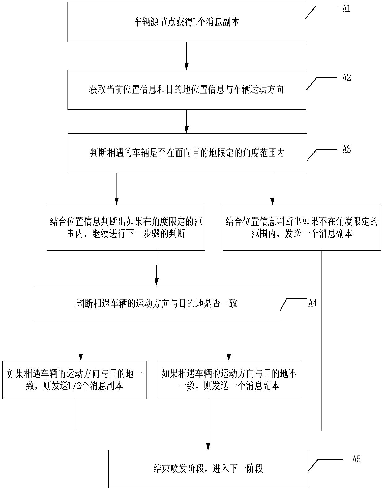
[0031] figure 1 It is a flowchart of the selective injection stage in the routing method of the present invention. As shown in the figure, in the present invention, the specific process of injection may include:
[0032] Step A1, the vehicle source node obtains L message copies.
[0033] Specifically, the value of L is usually determined according to the scale of the network, and the obtained value of L is generally much smaller than the number M of nodes in the network.
[0034] Step A2, obtaining the current location information, the target location information and the moving direction of the vehicle.
[0035] Specifically, all moving vehicles are equipped with a GPS system, so the information can be obtained more conveniently, and the vehicle keeps a neighbor list recording node information within a hop range.
[0036] Step A3, judging whether the oncoming vehicle is within the range limited by the angle facing the destination.
[0037] Specifically, in the injection phase, it is a waste of resources to blindly send message copies to all vehicles encountered. The present invention proposes to link the number of message copies forwarded by vehicles with the emission range, and within the emission range of the target-oriented vehicle , that is, within an angle range that is closer to the target vehicle, more message copies are emitted; if it is within the emission range facing away from the target vehicle, only one message copy is emitted.
[0038] Step A4, judging whether the moving direction of the encountered vehicle is consistent with the destination.
[0039] Specifically, the angle between the vector of the current vehicle to the destination and the direction of movement of the vehicle is calculated. If the included angle is less than π/2, it means that the driving direction of the vehicle is consistent with the direction of the destination, and at the same time, within the injection range of the target-oriented vehicle that satisfies step A3, a message copy of L/2 is sprayed to these neighbor nodes; if the included angle If it is greater than π/2, it means that the vehicle is traveling in the opposite direction to the destination, which will quickly leave the injection range, so only one copy of the message will be emitted.
[0040] Step A5, ending the eruption stage and entering the second stage.
[0041] Specifically, the erupted L copies are all carried by the vehicle node and enter the second stage.
[0042] In the embodiment of the present invention, compared with the traditional injection protocol, the moving vehicle distributes the data packets according to the location information with a certain orientation and purpose, without consuming too much network resources and without flooding blindly. It can also improve the delivery rate of messages.
[0043] figure 2 It is a flow chart of the stage of actively selecting the next hop in the routing method of the present invention. As shown in the figure, in this embodiment, the movement of the vehicle is dominated by human factors. The selection of the next hop in the forwarding process should consider how to comprehensively affect various factors that affect the efficiency of message copy forwarding, and choose a more suitable next hop. Jump, where the steps should include:
[0044] Step B1, obtain the basic information of the indicators to be calculated.
[0045] Specifically, through the interaction between vehicles, it is necessary to obtain basic information such as the encounter time, the vehicle's residence time in the network, the number of neighbor nodes, and the relative distance and relative speed.
[0046] Step B2, update and calculate the node recency.
[0047] Specifically, because the possibility of establishing a connection between vehicles in the future is closely related to the situation of establishing a connection recently, the recency index of the node is calculated, which is the time interval ratio of the last connection between vehicles. The shorter the time interval between the latest contact and the current time, the higher the probability of future contact. It can be defined as the ratio of the time interval between the last time a connection was established and the current time and the vehicle's residence time in the network. In order to make it more in line with the dynamics in the vehicle ad hoc network, the method of weighting the exponential movement with the previous state and the current state value is used to update the node, that is, the previous state accounts for 0.3, and the current state value accounts for 0.7. Proximity indicators.
[0048] Step B3, updating and calculating the node activity factor.
[0049] Specifically, the node activity factor represents the mobility of the vehicle, and the more active the vehicle, the more vehicles it can contact, and thus the greater the chance of encountering the destination. It is defined as the ratio of the average number of neighbor nodes of the vehicle over a period of time to the maximum number of neighbor nodes in the network.
[0050] In step B4, the three indicators use the FIS fuzzy logic system to evaluate the next hop with the best performance.
[0051] Specifically, first pass the relative speed and relative distance through the fuzzy logic system, and then combine the driver's behavior with a learning algorithm to obtain the acceleration of the vehicle, and then calculate the dynamic and accurate vehicle speed from the acceleration. Combining the node recency and node activity factor calculated in steps B2 and B3, these three indicators are used as input parameters to pass through a fuzzy logic system again. Firstly, the indicators are transformed into fuzzy values by using predefined linguistic variables and membership functions, and then the selection of the next hop is ranked by predefined rules, and finally the fuzzy output is converted into a value by an output membership function and defuzzification method, according to The result is routing.
[0052] In the embodiment of the present invention, different from the second stage of the basic routing protocol, the node carries a copy of the message and passively waits for the destination node to transmit the message to it, or waits for the lifetime of the message to discard the message. Vehicle nodes carrying message copies actively perform routing, which can deliver messages to their destinations faster.
[0053] see image 3 , image 3 It is the routing protocol proposed in the present invention that a message needs to carry multiple copies, so it needs to use a better caching strategy. Through the cache mechanism, messages with higher priority are sent out of the cache first, thus reducing the overall transmission delay of the routing algorithm, and also giving higher priority to messages with higher utility values in the cache during congestion. Thus increasing the throughput of the system.
[0054] Step C1, receiving data packets, and judging whether the buffer space is congested.
[0055] Specifically, in the in-vehicle network, the vehicle nodes are intermittently connected, and each node needs to use a cache to store messages that need to be transmitted, but the cache space is limited, so after receiving data packets, it is first necessary to determine whether the cache space is congested. This implementation In the example, it is assumed that the cache space is ξ, and when 3/4ξ of the cache space is used, it is judged that the cache is congested.
[0056] In step C2, it is determined that the cache is not congested.
[0057] Specifically, it is determined that the buffer space is not congested, indicating that it can continue to be used, and the received data packets can be buffered.
[0058] Step C3, when it is judged that the buffer is congested, calculate the priority function of the messages and sort them.
[0059] Specifically, when the buffer is congested, the priority function is calculated for the message i, and then the messages are sorted in descending order according to the priority of the messages, and then the messages are scheduled in the buffer from top to bottom. Messages with high priority enter the cache, and messages with low priority are discarded directly. Among them, the priority function of the message is defined as: the remaining time to live (TTL i ) and the initialization time to live (TTL) of all messages in the network o ) to the cache size of the node (BS m ) and the size of message i (S i ) ratio product, the specific formula is: Because the greater the remaining lifetime of the message i, the greater the probability that the message i can reach the destination, so the higher the priority; at the same time, the larger the cache of the node m, the higher the priority; and the larger the message i, that is S i The bigger it is, the bigger the cache is consumed.
[0060] In the embodiment of the present invention, the vehicle node needs to carry multiple copies, but the cache size is limited, so it is necessary to propose a cache management mechanism to increase network throughput and reduce transmission delay. Whether to receive transmitted messages, and which messages are discarded to make room for received transmitted messages will affect delivery rate, throughput and latency. Among them, the basic format of the message is as follows Figure 4.
[0061] In order to understand the embodiments of the present invention in more detail, specific application scenarios of the present invention are given below.
[0062] see Figure 5 , Figure 5 It is a schematic diagram of the scene where the injection range is determined in the present invention. Among them, S is the source vehicle node, and D is the destination node. Various vehicles are driving on the road. After the vehicle source node generates a message, it hopes to quickly send a copy of the message from the source node S to D. According to the geographic location of S and D, it can be calculated vector. Assume that the current driving direction of the vehicle is the unit vector and The included angle is θ, The orientation angle is θ SA =|θ th ±θ| (take + when the current vehicle is in the direction of true east, and take - when the current vehicle is in the direction of true north), The orientation angle is θ SB =|θ th ±θ| (take - when the current vehicle is in the direction of true east, and + when the current vehicle is in the direction of true north), where θ th It is 90 degrees, which is the range where the dichotomy method may be used for eruption, that is, within the range of the blue line close to the destination as shown in the figure, the dichotomy method may be used for jetting. Send 1 copy of the message outside the blue lined part, i.e. the back part. This differentiated treatment mode is adopted because the vehicles on the regional roads within this angle range are closer to the destination, and the chances of forwarding to the destination are greater, and the copy of the message can be delivered to the destination faster, so more messages are distributed A copy is given to vehicles within this area, so that the delivery rate can be improved and the delay can be reduced.
[0063] see Image 6 , Image 6 It is a schematic diagram of the scene of the injection stage combined with the vehicle movement direction in the present invention. The vehicle may travel in a direction away from the destination, which will carry its copy to a location farther and farther away from the destination node, causing a lot of waste on the number of copies of the message. S is the source vehicle node, D is the destination node, and the vehicle S carrying the message copy calculates the angle between the movement direction of the neighbor vehicle within one hop and the direction of the source node vehicle and the destination vector. This angle is the direction angle. If the direction angle is less than the angle threshold π/2, it means that the driving direction is consistent with the direction of the destination node. At this time, select the encountered vehicle that satisfies the above two angle ranges to send L/2 copies. If the direction angle is greater than π/2, it means that the driving direction of the vehicle is opposite to the direction of the destination, and only one copy is forwarded. As shown in the figure, assume that A and B satisfy at the same time Figure 5 within the defined spray area. φ1 and φ2 are the moving direction angles of two neighboring vehicles A and B of S respectively. Through calculation, φ1 is smaller than π/2, and φ2 is greater than π/2, so the number of message copies forwarded by node S to vehicle B is L/2, forward only 1 copy to A.
[0064] Finally, it should be noted that the above preferred embodiments are only used to illustrate the technical solutions of the present invention and not to limit them. Although the present invention has been described in detail through the above preferred embodiments, those skilled in the art should understand that it can be described in terms of form and Various changes may be made in the details without departing from the scope of the invention defined by the claims.