Wireless communication terminal device, wireless communication base station device and wireless communication method
A wireless communication terminal and control signal technology, applied in wireless communication, multiplexing communication, location diversity and other directions, can solve the problem of high possibility of adaptive control utilization
- Summary
- Abstract
- Description
- Claims
- Application Information
AI Technical Summary
Problems solved by technology
Method used
Image
Examples
Embodiment approach 1
[0059] [Structure of network system]
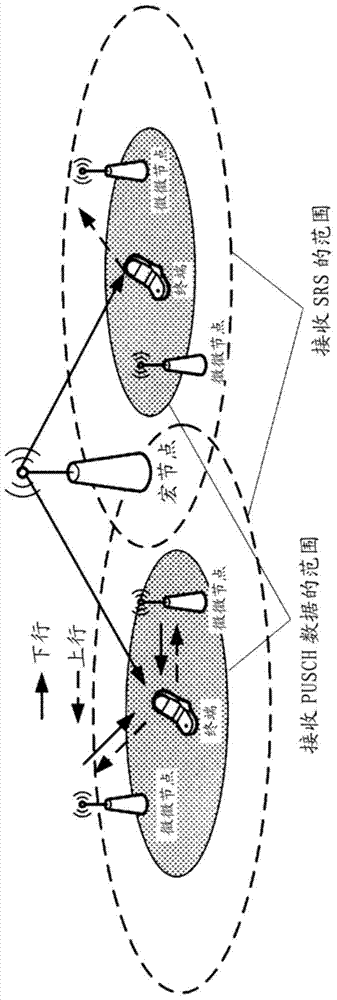
[0060] The network system of Embodiment 1 of the present invention is HetNet or HetNet CoMP, such as figure 1 As shown, it consists of a macro node 100 , a pico node 200 and a terminal (UE) 300 . In each macro cell, one macro node 100 and one or more pico nodes 200 are provided. Wherein, the pico node 200 may be a pico base station forming a separate pico cell, or may be a node such as RRH (Remote radio head, remote radio head) that communicates with a terminal as a part of a distributed transceiver antenna of a macro cell . The macro node 100 and each pico node 200 are connected by a low-latency, high-capacity interface such as an optical fiber. The macro node 100 and each pico node 200 in the cell share the transmission parameters of the SRS allocated to each terminal 300 existing in the cell, and receive the SRS to measure CSI. Each terminal 300 performs wireless communication with one or more nodes 100 and 200 selected by the macr...
Deformed example 1
[0099] In Embodiment 1, a case where closed-loop TPC of A-SRS is performed using DCI format 3 / 3A is described. However, it is also possible to use DCI format 3 / 3A to perform closed-loop TPC only for a specific A-SRS according to the instruction of the macro node 100 . The specific A-SRS refers to any one of the five types of A-SRS that has parameter sets set separately according to the type of DCI and the value of the transmission request bit as described above.
[0100] Among the DCIs including transmission request bits, DCI formats 0 / 4 are DCIs indicating uplink data allocation information, and DCI formats 1A / 2B / 2C are DCIs indicating downlink data allocation. In most cases, the traffic of packet data is bursty, so there is a high possibility that the allocation of PDSCH and PUSCH will be concentrated in time. In other words, there is a high possibility that DCI format 0 / 4 and PUSCH transmission or reception, or DCI format 1A / 2B / 2C, PDSCH, and PUCCH transmission or receptio...
Deformed example 2
[0103] It is possible to send DCI format 3 / 3A in all downlink subframes, but it can also be set to send TPCs containing A-SRS only in subframes or PRBs (Physical Resource Blocks) at specific times and time intervals Command DCI format 3 / 3A. Thereby, terminal 300 does not need to attempt decoding of DCI format 3 / 3A in all subframes, so that the processing load can be reduced. Furthermore, the base station nodes 100 and 200 only need to transmit the DCI format 3 / 3A of the A-SRS in subframes at specific times or time intervals, and thus can reduce the overhead caused by the transmission of TPC commands.
[0104] In addition, in the case where the DCI format 3 / 3A of the TPC command including A-SRS is transmitted or received only in subframes or PRBs of a specific time and time interval, the transmission opportunity of the TPC command of DCI format 3 / 3A is reduced . However, the A-SRS for closed-loop TPC using DCI format 3 / 3A is likely to be an SRS intended to be received by a no...
PUM
 Abstract
Description
Claims
Application Information
 - R&D
- Intellectual Property
- Life Sciences
- Materials
- Tech Scout
- Unparalleled Data Quality
- Higher Quality Content
- 60% Fewer Hallucinations
Browse by: Latest US Patents, China's latest patents, Technical Efficacy Thesaurus, Application Domain, Technology Topic, Popular Technical Reports.
© 2025 PatSnap. All rights reserved.Legal|Privacy policy|Modern Slavery Act Transparency Statement|Sitemap|About US| Contact US: help@patsnap.com


