Frictional heating insoles

A technology of friction heating and insoles, which is applied in footwear, clothing, applications, etc.

Inactive Publication Date: 2014-05-07
丁妍
View PDF6 Cites 6 Cited by
  • Summary
  • Abstract
  • Description
  • Claims
  • Application Information

AI Technical Summary

Problems solved by technology

The current insoles do not have self-heating insoles. Although there are electric insoles, they must be powered on, which is inconvenient.

Method used


Image

  • Frictional heating insoles

Examples


Embodiment Construction

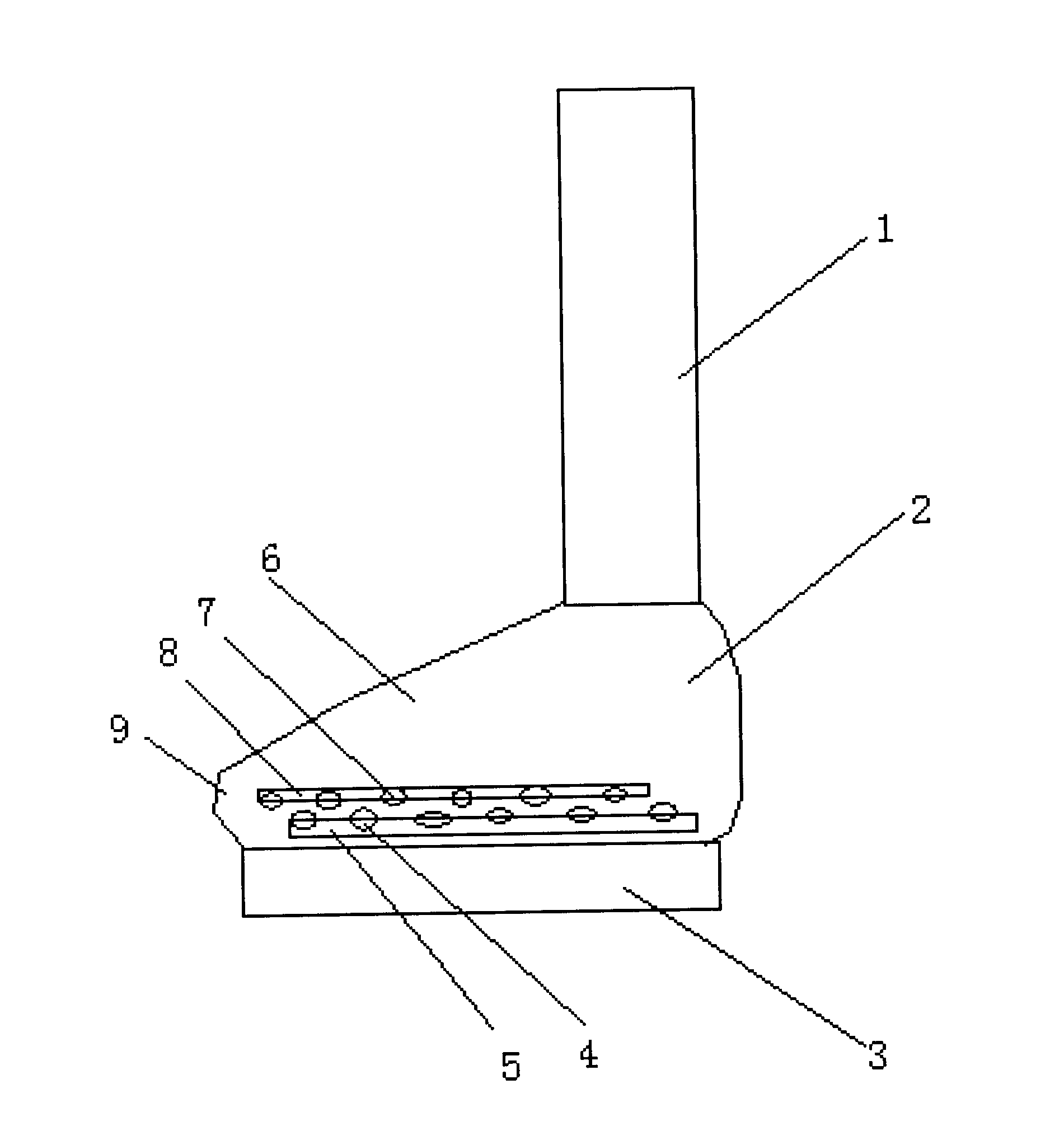
[0009] exist figure 1 In the shown embodiment, upper (1), heel (2), sole (3), lower friction plate (4), lower insole (5), shoes (6), upper friction plate (7), upper Insole (8), toe cap (9).

[0010] Implement the frictional heating insole of the present invention, comprising shoes (6), upper of a shoe (1), heel (2), sole (3), toe cap (9) connected in sequence, the shoe sole (3) is equipped with a lower insole (5), The lower friction plate (4) is installed on the surface of the lower shoe-pad (5), the upper shoe-pad (8) is installed above the lower shoe-pad (5), and the upper friction plate (7) is installed on the bottom surface of the upper shoe-pad (8). The lower friction plate (4) installed on the surface of the lower insole (5) and the upper friction plate (7) installed on the bottom surface of the upper insole (8) can have multiple.

[0011] Implement the friction heating insole of the present invention, when walking, use the movement of the sole of the foot to make the ...


PUM


Abstract

Frictional heating insoles comprise shoes, uppers, heels, soles and toes; the shoes, the uppers, the heels, the soles and the toes are connected in turn; lower insoles are arranged on the soles; the surfaces of the lower insoles are provided with lower friction sheets; upper insoles are arranged on the lower insoles; the bottom surfaces of the upper insoles are provided with upper friction sheets; the plurality of lower friction sheets can be arranged on the surfaces of the lower insoles and the plurality of upper friction sheets can be arranged on the bottom surfaces of the upper insoles. According to the frictional heating insoles, friction can be produced on the friction sheets which are arranged on the two insoles due to the movement of the soles during walking and accordingly heat can be generated to warm the soles and remove the foot sweat and accordingly the shoes can keep dry and frostbite can be avoided.

Description

1. Technical field [0001] The invention relates to a friction heating insole, in particular to a friction heating insole with a lower friction plate installed on the surface of the lower insole and an upper friction plate installed on the bottom surface of the upper insole. 2. Background technology [0002] When people walk, they often produce foot sweat, which makes the inside of the shoes damp, which will give birth to chilblains. The current insoles do not have self-heating insoles. Although there are electric insoles, they must be powered on, which is inconvenient. 3. Contents of the invention [0003] The purpose of the present invention is to overcome the deficiencies of the prior art and provide a friction heating insole with a lower friction plate installed on the surface of the lower insole and an upper friction plate installed on the bottom surface of the upper insole. [0004] The technical solution adopted by the present invention to solve the technical proble...

Claims


Application Information

Patent Timeline
Patent Type & Authority Applications(China)
IPC IPC(8): A43B7/34
Inventor 丁妍
Owner 丁妍
Why Eureka
Try Eureka