

Fuel cell system utilizing control of operating current to adjust moisture content within fuel cell
a fuel cell and control current technology, applied in the direction of secondary cell servicing/maintenance, electrochemical generators, transportation and packaging, etc., can solve the problem of difficulty in drying the interior of the fuel cell, the level of electric power produced by the fuel cell to be lowered, and the inability to maintain the fuel cell in a suitable internal moisture condition. , to achieve the effect of reducing the level of electric power produced by the fuel cell, and improving the service li
- Summary
- Abstract
- Description
- Claims
- Application Information
AI Technical Summary
Benefits of technology
Problems solved by technology
Method used
Image

Examples
first embodiment
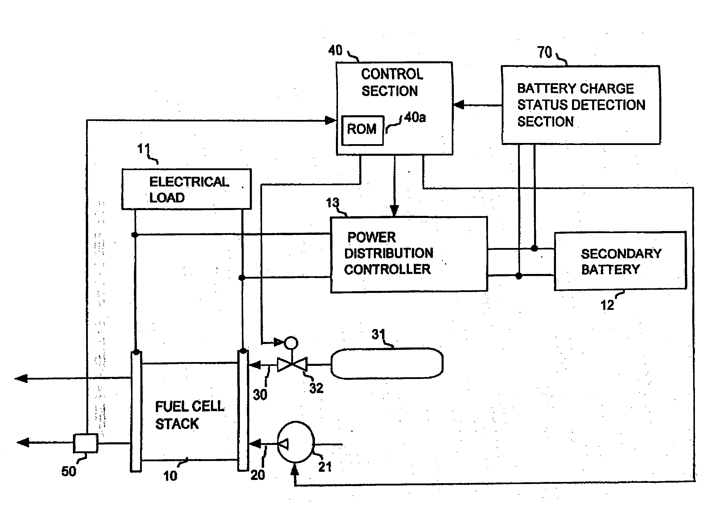
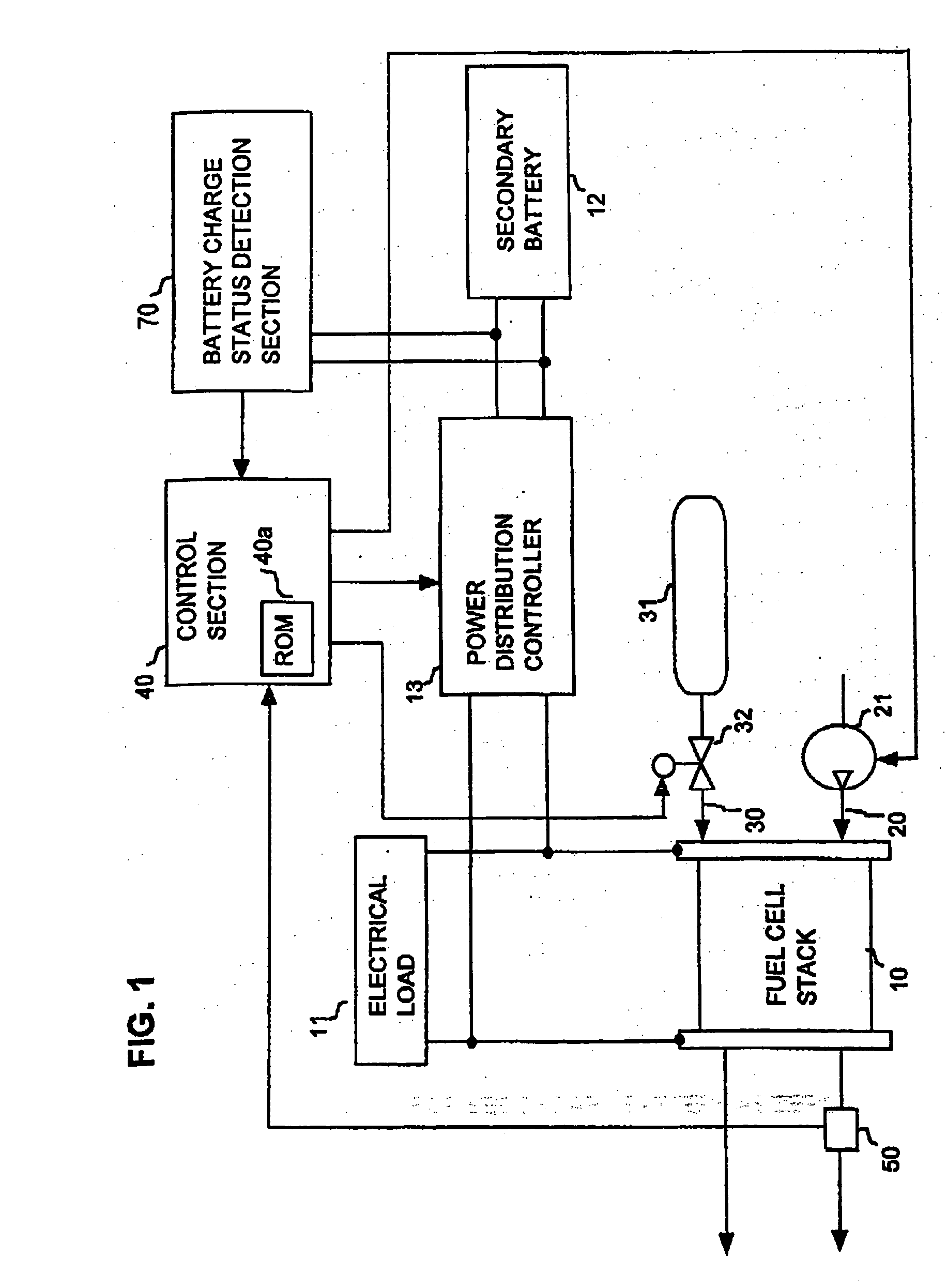
[0033] A first embodiment will be described referring to FIGS. 1 to 5. This embodiment is a fuel cell system that is utilized as the motive power source of an electric vehicle. FIG. 1 is a conceptual system diagram showing the overall configuration of the embodiment. As shown in FIG. 1, the system is based on a fuel cell stack (i.e., battery of series-connected fuel cells) 10, which generates power by an electrochemical reaction between hydrogen and oxygen. With this embodiment, a polymer fuel cell is used for each of the series-connected fuel cells of the fuel cell stack 10. Each of these fuel cells is made up of a pair of electrodes with an electrolyte membrane sandwiched between them. By supplying hydrogen and oxygen (i.e., as air) to the fuel cell stack 10, electrical energy is generated by the aforementioned electrochemical reaction. The reactions which occur at the respective electrodes are as follows:
[0034] At the hydrogen side: H.sub.2.fwdarw.2H.sup.++2e.sup.-
[0035] At the o...
second embodiment
[0072] A second embodiment of a fuel cell system will be described referring to FIG. 6 and FIGS. 7A, 7B. FIG. 6 is a conceptual system diagram of this embodiment, in which components corresponding to those of the embodiment of FIG. 1 are designated by identical reference numerals to those of FIG. 1, with further description of these being omitted. The system is based on two fuel cell stacks 10A, 10B, which are respectively separately controlled. Overall control of the system is performed by a control section 140, which controls each of the compressor 21, air distribution adjustment valve 22, hydrogen distribution adjustment valve 33 and power distribution controller 13. The flow of air from the compressor 21 is divided into two paths, at a location upstream from the air distribution adjustment valve 22 and the fuel cell stacks 10A, 10B, i.e., a flow path 20A which supplies a flow of air to the fuel cell stack 10A, and a flow path 20B which supplies a flow of air to the fuel cell sta...
third embodiment
[0088] A third embodiment of a fuel cell system will be described referring to the conceptual system diagram of FIG. 8 and the flow diagram constituted by FIGS. 9A, 9B. In FIG. 8, components corresponding to those of the embodiment of FIG. 6 are designated by identical reference numerals to those of FIG. 6, with further description of these being omitted in the following. As shown in FIG. 8, the system is based on two fuel cell stacks 10A, 10B which are respectively separately controlled, with a control section 240 performing overall control of the system, including control of respective levels of power that are produced by the fuel cell stacks 10A, 10B, by supplying command signals to the power distribution controller 113 designating respective values of operating current that are to be generated by the fuel cell stacks 10A, 10B so that the required values of generated power will be achieved, and with the power distribution controller 113 performing control of the respective operat...
PUM
 Abstract
Description
Claims
Application Information