
Structure of concrete delivery pump

A concrete conveying pump and concrete technology, applied in pumps, components of pumping devices for elastic fluids, piston pumps, etc., can solve problems such as failure to work normally, short life of hydraulic cylinders and conveying cylinders, and high energy consumption. Achieve the effect of overcoming short lifespan or even failure to work normally

Inactive Publication Date: 2014-05-07
JIANGSU BADA HEAVY IND MACHINERY
View PDF0 Cites 1 Cited by
  • Summary
  • Abstract
  • Description
  • Claims
  • Application Information

AI Technical Summary

Problems solved by technology

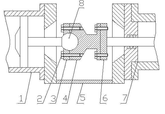
[0005] Beneficial effects: Since the ball joint composed of the ball head and the ball head seat has the function of a universal joint, it can compensate for the error that the piston rod of the feeding cylinder and the piston rod of the hydraulic cylinder cannot be on the same axis, so, The present invention can overcome the defects that the lifespan of the hydraulic cylinder and the conveying cylinder in the prior art is short or even unable to work normally, and overcome the defect that the energy consumption is high due to the abnormal increase of the movement resistance

Method used


Image

  • Structure of concrete delivery pump

Examples


Embodiment Construction

[0010] In the figure, the structure of the concrete Shusihong pump includes: feeding cylinder 1, bolt 2, spherical cover plate 3, ball head seat 4, water tank 5, flange 6, hydraulic cylinder 7, ball head 8, feeding cylinder 1 and the cylinder body of the hydraulic cylinder 7 are symmetrically installed and fixed on both sides of the water tank 5, a ball head 8 is fixed at the end of the piston rod of the feeding cylinder 1, and a flange is fixed at the end of the piston rod of the hydraulic cylinder 7 6. The ball head 4 is set between the ball head 8 and the flange 6, wherein the ball head 8 sinks in the ball socket on the ball head seat 4, and the ball head 8 is fixed on the Together, the other end of the ball head seat 4 is fixedly connected to the flange 6 with bolts 2 .


PUM


Abstract

The invention discloses a structure of a concrete delivery pump. A delivery cylinder and a hydraulic cylinder body are symmetrically installed and fixed on two sides of a water tank, a ball head is fixed at the end of a piston rod of the delivery cylinder, a flange is fixed at the end of the piston rod of the delivery cylinder, a ball head seat is arranged between the ball head and the flange, the ball head sinks in a ball socket on the ball head seat, the ball seat is connected through a spherical surface cover plate and a bolt, and the other end of the ball head seat is fixedly connected with the flange through a bolt. The defect that a hydraulic cylinder and the delivery cylinder are short in service life and even cannot normally work in the prior art is overcome, and the defect of high energy consumption due to the fact that motion resistance is increased abnormally is overcome.

Description

technical field [0001] The invention relates to the structure of a conveying pump, in particular to a structure of a concrete conveying pump, which belongs to the structural technical field of concrete conveying pumps. Background technique [0002] At present, the structure of the concrete delivery pump is all composed of a feeding cylinder, a water tank and a hydraulic cylinder. The feeding cylinder and the hydraulic cylinder are installed on both sides of the water tank, and the piston rod of the feeding cylinder and the piston rod of the hydraulic cylinder pass through. The two sides of the water tank are rigidly connected and fixed together. The concrete delivery pump with this structure will inevitably produce errors in the process of manufacturing and installation, which will easily cause the piston rod of the delivery cylinder and the piston rod of the hydraulic cylinder to be inconsistent. They are on the same axis, so it is easy to cause one-way wear (ie: eccentri...

Claims


Application Information

Patent Timeline
Patent Type & Authority Applications(China)
IPC IPC(8): F04B53/00F04B9/105
Inventor 陈利明
Owner JIANGSU BADA HEAVY IND MACHINERY
Learn More