
Anti-fall control device for tower crane lifting

A control device and jacking technology, which is applied in the direction of cranes, etc., can solve the problems of large distance between the center of the climbing claw beam and the step, inability to effectively lock the jacking beam, low safety and reliability, etc., and achieve low labor intensity and low operating force. small, simple structure

Active Publication Date: 2014-05-14
XUZHOU CONSTR MACHINERY
View PDF11 Cites 5 Cited by
  • Summary
  • Abstract
  • Description
  • Claims
  • Application Information

AI Technical Summary

Problems solved by technology

This structural form has the following disadvantages: (1) During the climbing and descending process of the climbing frame, the climbing claw needs manual assistance when stepping through the standard joint, which poses a safety hazard
(2) During the jacking process, the climbing claws need to be manually rotated when the climbing claws pass through the steps, and the work intensity is high
Due to the limitation of the structure size of the crawler, the distance between the center of the crawler beam and the step is large, the crawler beam needs to bear a large eccentric torque, the crawler beam needs to be locally strengthened, and the structure is heavy
(3) The supporting pin shaft of the jacking beam is placed in the circular groove at the upper end of the step, and the Φ20mm lock pin is used to prevent it from falling out. The diameter of the anti-dropping pin is small. Once the misoperation of the oil receiving cylinder occurs, the jacking beam cannot be effectively locked. Safety and low reliability

Method used


Image

  • Anti-fall control device for tower crane lifting
  • Anti-fall control device for tower crane lifting
  • Anti-fall control device for tower crane lifting

Examples


Embodiment Construction

[0025] The present invention will be further described below in conjunction with accompanying drawing.

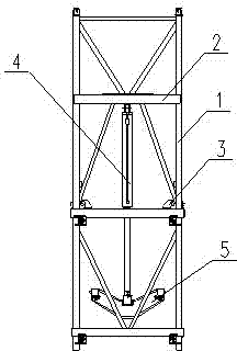
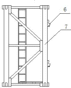
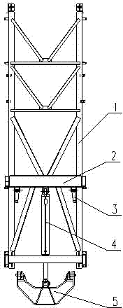
[0026] Such as Figure 3 to Figure 5 As shown, a tower crane jacking prevention control device of the present invention includes a climbing frame 1 and a step 6, and the climbing frame 1 includes a cylinder beam 2, a jacking cylinder 4 and a jacking beam 5, and the cylinder beam 2 is Climbing claws 3 are installed; the step 6 is installed on the outside of the standard section, the climbing claws 3 are suspension pawls, and the suspension pawls are hinged to the lug plate 2- welded on the cylinder beam 2 through the pawl shaft 3-1 1, the distance between the center of the pawl shaft 3-1 and the main chord 7 of the standard section is less than the length of the suspension pawl, and the climbing pawl 3 of the climbing frame 1 is a suspension pawl, and the suspension pawl is in a vertical position, when the climbing frame 1 passes through the step 6 on the main chord 7 of th...


PUM


Abstract

The invention discloses an anti-fall control device for tower crane lifting, belonging to the technical field of tower cranes. The anti-fall control device comprises a climbing frame (1) and steps (6), wherein the climbing frame comprises an oil cylinder beam, a lifting oil cylinder and a lifting beam, and climbing claws (3) are arranged on the oil cylinder beam; the steps are arranged on the outer side of a standard joint, the climbing pawls are suspension pawls which are articulated onto lug plates (2-1) welded on the oil cylinder beam through a pawl shaft (3-1), and the distance between the center of the pawl shaft and a main chord member of the standard joint is smaller than the length of each suspension pawl; fixing holes (6-1) for supporting lifting beam supporting shafts (5-2) are formed in the middles of the steps, and positioning grooves (6-2) are formed in the upper end and the lower end; telescopic mechanisms are arranged at two ends of the lifting beam. Manual operation is not required when the climbing frame passes through the standard joint steps, the lifting beam penetrates into the central hole of the standard joint step through a telescopic supporting shaft, the telescopic supporting shaft is positioned by using a safety pin so that telescopic misoperation of the oil cylinder is prevented, and the safety and reliability are high.

Description

technical field [0001] The invention relates to an anti-off control device, in particular to an anti-off control device for tower crane jacking, belonging to the technical field of tower cranes. Background technique [0002] According to statistics, tower crane accidents mostly occur during the installation and disassembly process, and the safety problems during jacking are particularly prominent. In existing designs, such as figure 1 with figure 2 As shown, the climbing frame 1 of the tower crane mainly includes the oil cylinder beam 2, the climbing claw 3, the jacking cylinder 4 and the jacking beam 5, and the climbing frame 1 is supported on the upper end surface of the step 6 of the main chord 7 of the standard section through the climbing claw 3 The upper and lower parts are connected to the jacking beam 5 through the jacking cylinder 4, and are supported in the circular groove of the step 6. The conversion support of the jacking beam between the up and down steps i...

Claims


Application Information

Patent Timeline
Patent Type & Authority Applications(China)
IPC IPC(8): B66C23/62
Inventor 王建军米成宏李雪亮姜华王磊周瑜
Owner XUZHOU CONSTR MACHINERY
Learn More